
Date:2025-07-22 Views:1005
Among all hydraulic motors, in-line piston pumps are the most advanced due to their unlimited pressure and displacement selection. These pumps can generate pressures up to 34.5MPa but are the most complex and expensive. They are typically used in high-efficiency mobile applications. In in-line piston pumps, four types of powder metallurgy parts are currently used: cylinder bodies, piston shoes, shoe plates or compression plates, and spherical washers (Figure 9-41). Powder metallurgy is the most economical method for producing these parts. However, when the cylinder body exceeds a size of 3.3×10⁻⁵ m3 and a mass of approximately 2.3kg, it loses its competitive advantage.
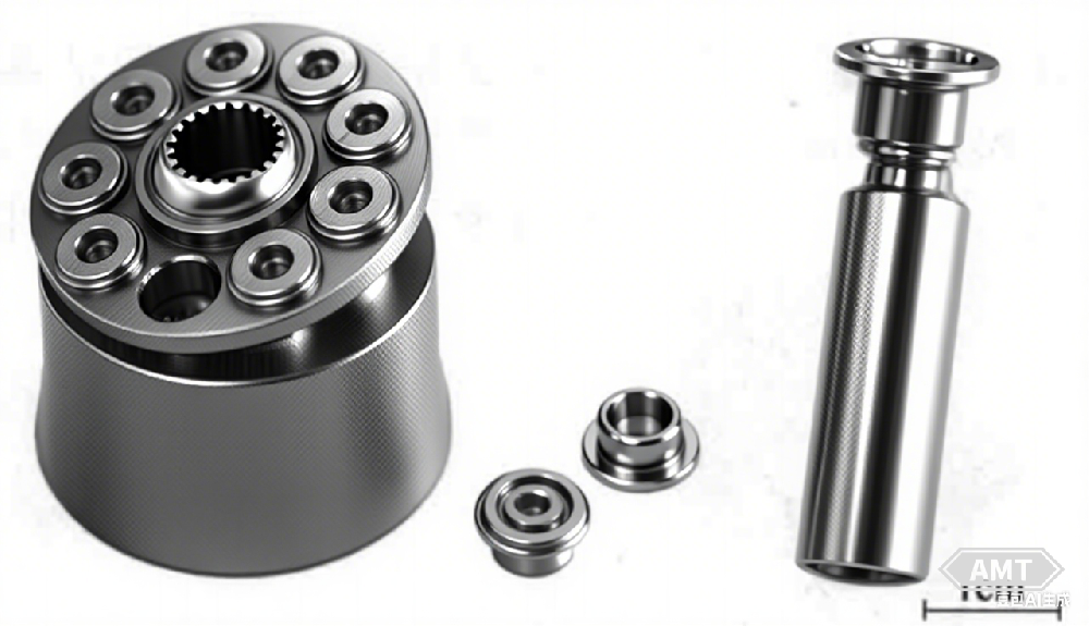
Figure 9-41 In the rotating section of an in-line piston pump, there are 4 parts that can use powder metallurgy parts: cylinder body, compression plate, spherical washer, and piston shoe
Production research using copper-infiltrated powder metallurgy steel as the cylinder body material indicates that powder metallurgy can eliminate several machining operations without increasing processing time:
Slotting, which increases rough turning rates, offsetting the time and tooling required for surface slotting.
Rough drilling of piston holes.
Drilling of oval grooves.
Heat treatment.
Finish turning.
Although the cost of powder metallurgy parts is double that of cast iron, the reduced machining time and labor lower production costs. Users can eliminate three machining stations. Technically, it meets the requirement of enhancing the positional accuracy of oval grooves relative to piston holes, a feasible feature.
Given that in-line piston pumps are used in high-pressure applications up to 34.5MPa and higher, the stress on the parts is a primary concern. Therefore, the strength and durability of highly loaded parts have been analyzed.
The cylinder body typically fails due to piston holes. To determine the maximum stress level of the selected material, stress levels were calculated using several criteria. Remember that fatigue life is 2.5 times the stress level. Below is the stress calculation for piston cylinder holes.
Three methods were used to analyze the strength near the piston cylinder holes (Figure 9-42):
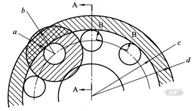
Figure 9-42 Stress Analysis Diagram near Piston Cylinder Bore
Method 1: Maximum Circumferential Stress (S2).
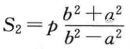
Where p is the pressure in the piston crown's internal pressure chamber.
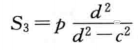
Maximum radial stress (S3):
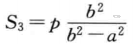
Assuming a maximum pressure of 23.7MPa, α = 6.0mm, b = 8.9mm, then S2 = 62.9MPa, S3 = 43.2MPa.
Method 2: Maximum Circumferential Stress (S2).
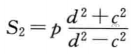
Where p is the pressure in the piston crown's internal working chamber, assumed to act on the entire internal surface of the pressure chamber.
Maximum radial stress (S3):
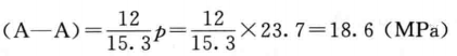
Method 3: Stress calculation with pressure lines = hole diameter = 12mm.
The stress area length equals 15.3mm, and the stress along section A-A is:
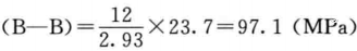
The stress area length equals 2.93mm, and the stress along section B-B is:
Leave your email for more ebooks and prices📫 !
Contact:Fidel
Tel:021-5512-8901
Mobile:19916725893
Email:sales7@atmsh.com
Address:No.398 Guiyang Road Yangpu China