
Date:2025-07-07 Views:0
Table of contents
Welded Power Take-Off (PTO) Handle
Neutral Arm for Front-Mounted Lawn Mower
Shaft-Type Cultivator Gear Assembly
Application of Powder Metallurgy Parts in Horticultural Machinery
Applications of powder metallurgy parts in riding mowers.
The welded PTO handle is a powder metallurgy cam used for starting switches. When the PTO handle is engaged, the cam is positioned in the neutral position of the starting system. The features of this powder metallurgy cam include straight side walls, small tolerances, and the ability to perform multiple functions without machining. The cam is welded onto the handle. To ensure smooth welding, the powder metallurgy cam must not be pre-lubricated before welding.
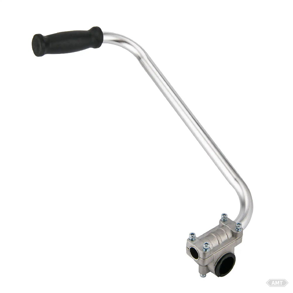
Figure 8-20 Welded PTO Handle
Table 8-16 Composition and Properties of Welded PTO Handle
Item | Performance |
MPIF Material | F-0008-P |
Carbon Content/% | 0.6~1.0 |
Iron Content/% | 97.0~99.1 |
Density/(g/cm3) | 6.4~6.8 |
Finished Product Quality/kg | 0.055 |
The PTO cam and follower are used to engage the PTO, which generally drives the lawn mower. When the follower rotates 30 radians, the cam moves along the spiral inclined surface, causing a 90° change in motion, transforming it into axial drive shaft motion. The shaft moves axially to engage and disengage the PTO. The design of this assembly, utilizing these two powder metallurgy parts, significantly reduces production costs. These two powder metallurgy parts not only replace riveted components but also make the surrounding parts easier to manufacture.
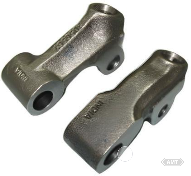
Figure 8-21 PTO Cam and Follower
Table 8-17 Composition and Properties of PTO Cam and Follower
Item | Cam | Follower |
MPIF Material | FC-0208-P | FC-0208-R |
Carbon Content/% | 0.6~1.0 | 0.6~1.0 |
Copper Content/% | 1.5~3.9 | 1.5~3.9 |
Iron Content/% | 93.1~97.9 | 93.1~97.9 |
Density/(g/cm3) | 6.0~6.4 | 6.4~6.8 |
Additional Requirements | Vapor treatment, oil impregnation | Vapor treatment, oil impregnation |
Finished Product Quality/kg | 0.209 | 0.168 |
The idler pivot is a part used to tension the belt clutch on lawn and garden tractors. By selecting powder metallurgy for this part, certain components can be integrated into a single design, eliminating the need for two positioning pins. To improve toughness, local copper infiltration is performed at the positioning pin locations. To enhance corrosion resistance, the part is oil impregnated.
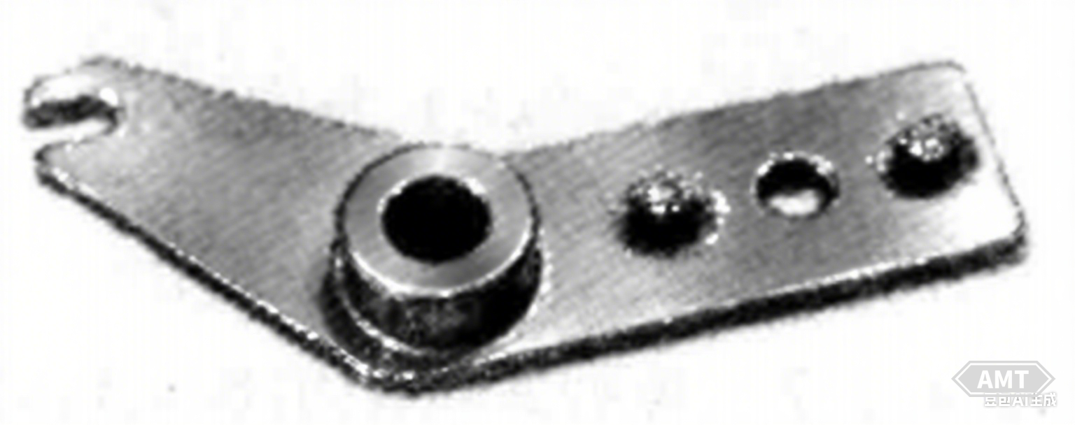
Figure 8-22 Idler Pivot
Table 8-18 Composition and Properties of Idler Pivot
Item | Performance |
MPIF Material | FC-0208-R |
Carbon Content/% | 0.6~1.0 |
Copper Content/% | 1.5~3.9 |
Iron Content/% | 93.1~97.9 |
Density/(g/cm3) | 6.4~6.8 |
Additional Requirements | Copper infiltration of two 6.35mm holes, oil impregnation |
Finished Product Quality/kg | 0.164 |
The hub is used on small lawn and garden tractors and some lawn mowers. This hub is an improved design that replaces the welded hub/shaft assembly to reduce production costs. The new design features a powder metallurgy hub threaded onto a forged steel shaft. Originally, the material specified for manufacturing the hub was MPIFFC-0208-R. Later, to improve impact performance, the material specification was changed to MPIFFN-0400-R.
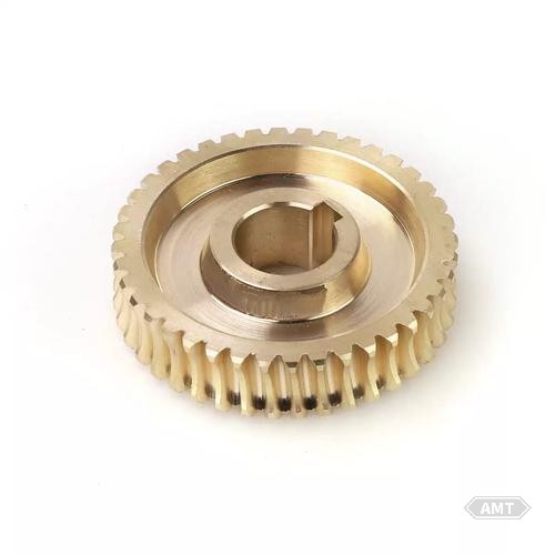
Figure 8-23 Lawn Mower Hub
Table 8-19 Composition and Properties of Lawn Mower Hub
Item | Performance |
| MPIF Material | FN-0400-R |
Carbon Content/% | 0.15~0.30 |
Copper Content (Maximum)/% | 2.0 |
Nickel Content/% | 3.0~5.5 |
Iron Content (Minimum)/% | 90.2 |
Density/(g/cm3) | 6.4~6.8 |
Apparent Hardness/HRB | 30~50 |
Finished Product Quality/kg | 0.318 |
Front-mounted lawn mowers are used for large areas like golf courses and cemeteries, where their high flexibility is advantageous. The neutral arm (Figure 8-24 and Table 8-20) controls the hydraulic-driven neutral return linkage of the front-mounted mower. The powder metallurgy neutral arm has a simple shape but precise tolerances, with three unequally spaced holes assembled in one orientation. The notch at the arm end ensures correct positioning.
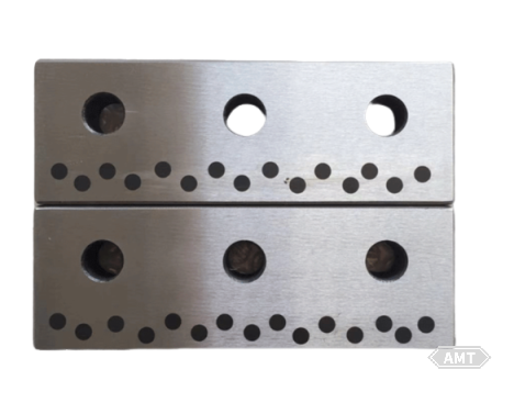
Figure 8-24 Neutral Arm for Front-Mounted Lawn Mower
Table 8-20 Composition and Properties of Neutral Arm for Front-Mounted Lawn Mower
Item | Performance |
MPIF Material | FN-0205-S |
Carbon Content/% | 0.3~0.6 |
Nickel Content/% | 1.0~3.0 |
Copper Content (max)/% | 2.5 |
Iron Content/% | 91.9~98.7 |
Density/(g/cm3) | 6.8~7.2 |
Additional Requirements | Oil Impregnation |
Finished Product Quality/kg | 0.090 |
Lawn and garden tractors require gears that can withstand extreme wear and heavy loads. The 4th gear reduction gear shown in Figure 8-25 and Table 8-21 is a driving gear in a six-speed transmission. The technical specifications require a single-tooth crushing load of 4000kg. The gear teeth of the powder metallurgy gear need to have high density. To achieve this, the part needs to be compacted to a density of 7.3~7.5g/cm3. However, the part is too large to be compacted on a 500t press. Therefore, the part is compacted to three different densities: hub density of 6.4~6.6g/cm3, inner flange density of 6.6~6.8g/cm3, and gear tooth density of 6.9~7.0g/cm3.
After pre-sintering, only the gear teeth are repressed to a density of 7.3~7.5g/cm3;. To improve compressibility during repressing, low-carbon content raw powders are used. After repressing, the gear teeth are carburized.
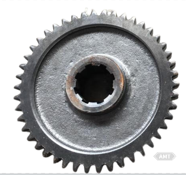
Figure 8-25 4th Gear Reduction Gear
Table 8-21 Composition and Properties of 4th Gear Reduction Gear
Item | Performance |
MPIF Material | FN-0205 |
Carbon Content/% | 0.5 |
Nickel Content/% | 2.0 |
Aluminum Content/% | 0.5 |
Density/(g/cm3) | 7.3~7.5 |
Inner Convex Edge | 6.6~6.8 |
Hub | 6.4~6.6 |
Apparent Hardness of Gear Teeth/HRC | 50~56 |
Crushing Strength of Gear Teeth/kN | 40 |
Finished Product Quality/kg | 1.042 |
The shaft-type cultivator gear assembly consists of a single pressed-sintered gear and sprocket. After sintering, the gear and sprocket are pressed together and copper infiltration is used for in-situ copper welding during the additional sintering process. Machining operations are limited to honing holes and pressing in needle bearings.
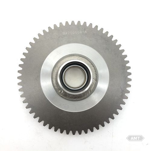
Figure 8-26 Shaft-Type Cultivator Gear Assembly
Table 8-22 Composition and Properties of Shaft-Type Cultivator Gear Assembly
Item | Gear | Sprocket |
MPIF Material | FN-0205-T | FN-0208-R |
Carbon Content/% | 0.5 | 0.6~0.9 |
Nickel Content/% | 2.0 | 1.0~3.0 |
Copper Content (max)/% | 0.5 | 2.5 |
Molybdenum Content/% | 0.5 | - |
Iron Content/% | - | 91.6~98.4 |
Density/(g/cm3) | 7.2~7.4 | 6.6~6.8 |
Eject Force/kN | 67 | - |
Finished Product Mass/kg | 0.485 | 0.485 |
Additional Requirements | After full sintering, press fit together and use local copper melting to infiltrate for copper welding. |
These include garden tractors, riding mowers, walk-behind mowers, shaft-type cultivators, lawn sweepers, shredders/ditchers, chainsaws, and snow blowers.
Gearing in the gearbox of gardening tractors with power less than 11768W uses powder metallurgy gears, as shown in Figure 8-27. These gears are made of powder metallurgy nickel steel. The gear teeth end face is pressed into a wedge shape, as shown in Figure 8-28. This not only eliminates subsequent machining and forms a better roughness but also makes the mutual impact more stable. The improved roughness and the improved uniformity of the gears combine to significantly reduce the operating noise of the gearbox.
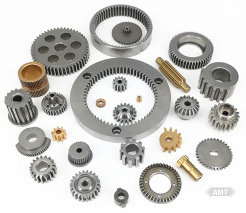
Figure 8-27 A typical combination of powder metallurgy gears used in the gearbox.
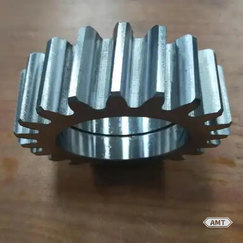
Figure 8-28 Wedge shape of the gear teeth end face.
Shifting forks in the gearbox (Figure 8-29) are mostly made of copper - infiltrated steel. In most cases, subsequent machining is needed. Considering production costs, this type of part is most suitable for manufacturing with powder metallurgy processes.
The parts in the limited - slip differential (Figure 8-30) are not only gears but also end caps and other parts, such as washers and body cores. These are all manufactured using powder metallurgy processes from high - strength powder metallurgy materials.
Many steering mechanisms of gardening tractors use bevel gears and pinion gears produced by powder metallurgy processes, as shown in Figure 8-31.
Powder metallurgy parts used in braking and clutch mechanisms include brake drums, linings, and brackets, as shown in Figure 8-32.
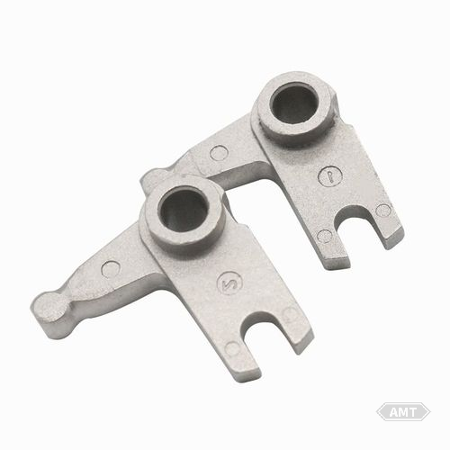
Figure 8-29 A Set of Typical Powder Metallurgy Shifting Forks
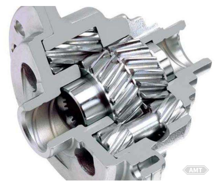
Figure 8-30 Limited-Slip Differential Using Powder Metallurgy Gears, Washers, and Carrier Cover Plate
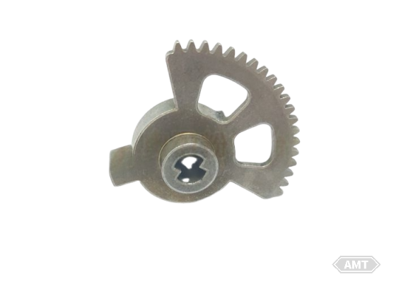
Figure 8-31 Powder Metallurgy Bevel Gears and Pinion Gear in Steering Mechanism
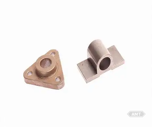
Figure 8-32 Typical Powder Metallurgy Brackets and Bushings
Another application of powder metallurgy is spline hubs (Figure 8-33). After manufacturing the spline hub via powder metallurgy processes, it is die - cast into a wheel. This creates a wheel with a wear - resistant precision spline inner diameter.
Most gardening tractors are equipped with mower attachments. In these attachments, powder metallurgy parts are evident. Representative parts include blade carriers and blade shear bushings (Figure 8-34). These parts are specially made using powder metallurgy processes to fracture upon impact with a certain load, thus preventing damage to the device when the blade hits an obstacle.
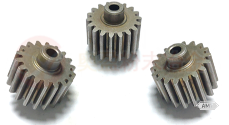
Figure 8-33 Powder metallurgy hub (showing the spline inner diameter, flange, and outer diameter spline fixed in the die - cast wheel).
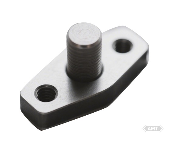
Figure 8-34 Powder Metallurgy Lawn Mower Blade Carrier
In riding mowers, the gearboxes almost entirely use gears produced by powder metallurgy processes. In most cases, the complete gearbox assembly (Figure 8-35) is bolted onto the mower. Gears in small - horsepower gearboxes are made from general powder metallurgy Fe - C alloy materials. Gears in higher - horsepower gearboxes are made from copper - infiltrated nickel steel using powder metallurgy processes. To enhance strength and durability, the gears undergo heat treatment. Shifting forks in the gearbox are also manufactured using powder metallurgy processes.
The equal - diameter bevel gears and washers used in the differentials of riding mowers (Figure 8-36) are also produced using powder metallurgy processes, using the same materials as the gears in the gearbox. Some riding mowers with limited - slip differentials use all powder metallurgy gears instead of bevel gears. This is because these differentials have lower loads than those in gardening tractors, requiring lower gear material strength.
The bevel gears and pinion gears used in the steering mechanisms of riding mowers (Figure 8-37) are also produced using powder metallurgy processes.
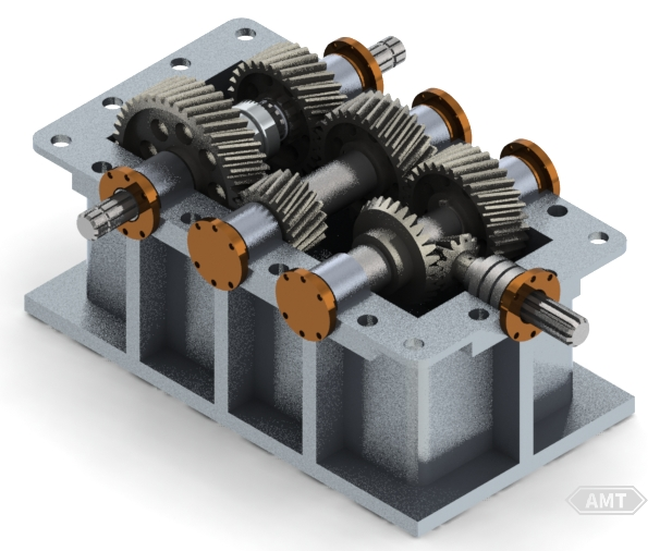
Figure 8-35 A typical gearbox using powder metallurgy gears.
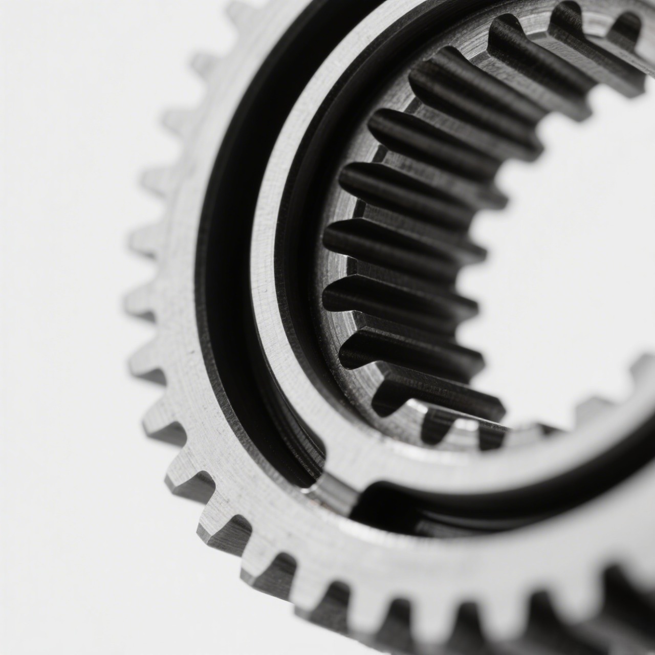
Figure 8-36 A cross-section of a powder metallurgy bevel gear.
(1) Walk - behind mowers.
Some self - propelled devices of these mowers have a two - speed transmission pinion gearbox. Powder metallurgy parts in the direct - drive devices include sprockets, right - angle bevel gear drives, and hubs that prevent tire movement. Like gardening tractors and riding mowers, walk - behind mowers also use blade carriers and bushings.
(2) Shaft - type tillers.
The complete set of powder metallurgy gears used in the transmission of shaft - type tillers is shown in Figure 8-38. These gears have essentially the same characteristics as those used in gardening tractor gearboxes. Additionally, shift forks and shift rod guide balls in the transmission are also produced using powder metallurgy processes.
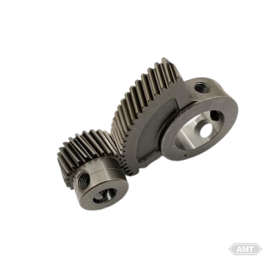
Figure 8-37 Powder metallurgy bevel gears and pinion gears used in the steering mechanism of a riding mower.
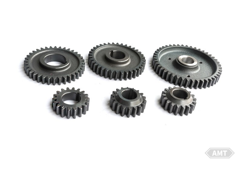
Figure 8-38 Complete set of powder metallurgy gears used in the transmission of a shaft - type tiller.
(3) Lawn sweepers.
The most commonly used powder metallurgy parts in these sweepers are two stop ratchet wheels at the ends of the brush assembly. This mechanism allows the brush to rotate only in the forward direction.
(4) Shredders/ditchers.
These devices are similar to lawn mower blade carriers.
(5) Chainsaws.
The sprocket that drives the cutting chain in chainsaws is manufactured using powder metallurgy processes. Typically, the powder metallurgy sprocket is tack welded to a carbon - copper clutch drum. Another application is in electric chainsaws as part of the electric motor transmission mechanism. In this case, the heat - treated powder metallurgy sprocket and the untreated internal gear powder metallurgy cover are assembled together (Figure 8-39).
This system also connects powder metallurgy gears to the electric motor shaft. The heat - treated powder metallurgy sprocket is formed within a plastic cover similar to the powder metallurgy cover used in lower - cost electric chainsaws.
Centrifugal clutch transmission mechanisms extensively use powder metallurgy parts. The central hub and two shoe components are typically produced using powder metallurgy processes, as shown in Figure 8-40.
(6) Snow blowers.
The forward and reverse gears in the transmission mechanisms of snow blowers are manufactured using powder metallurgy processes.
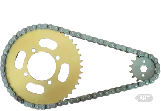
Figure 8-39 A component assembly of powder metallurgy sprockets and covers with chains and guide plates.
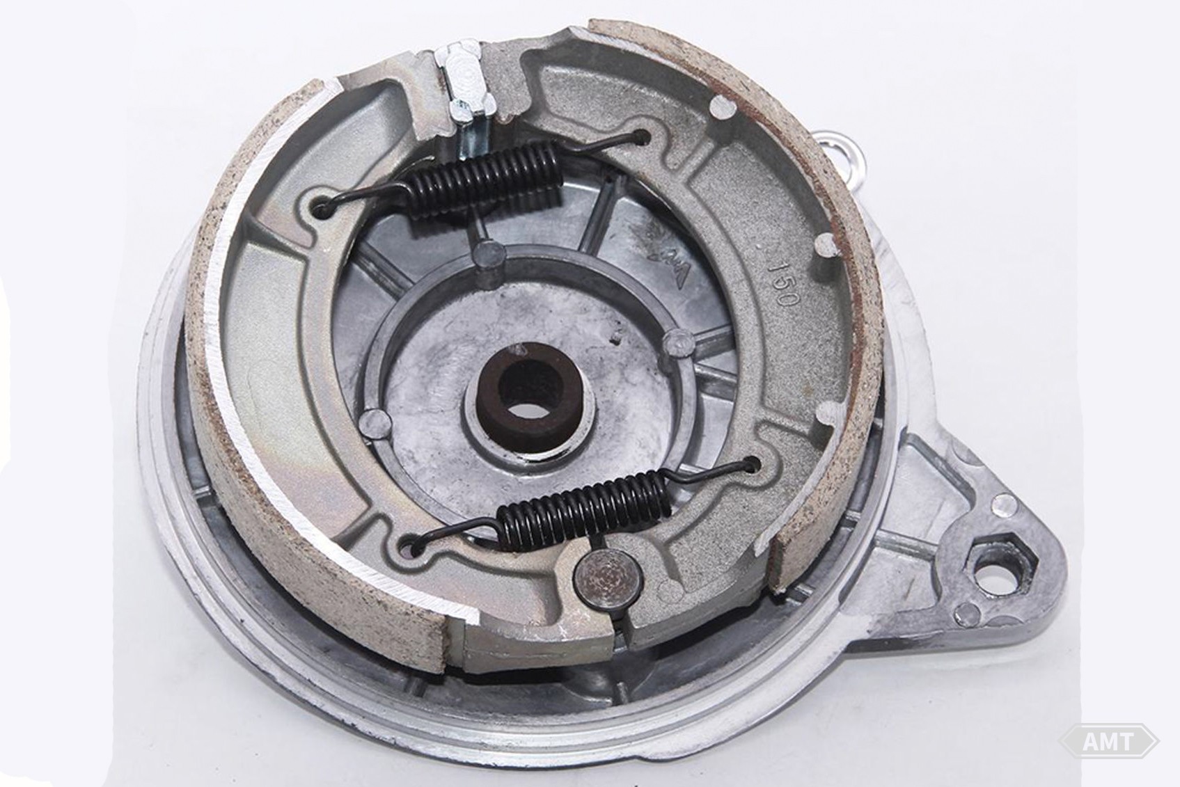
Figure 8-40 Typical centrifugal clutch drive components with powder metallurgy hubs and shoes.
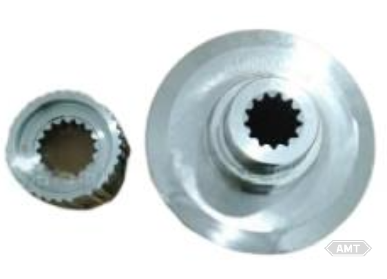
Figure 8-41 Lawn mower blade brake - clutch output hub.
The above introduces powder metallurgy parts used in lawn and gardening machinery in the 1970s. In the past 40 years, significant progress has been made in powder metallurgy processes and materials.
(1) Lawn mower blade brake - clutch output hub (Figure 8-41).
These powder metallurgy parts have a density of 6.7g/cm3;. Their properties include: ultimate tensile strength of 414MPa, yield strength of 380MPa, fatigue strength of 345MPa, and hardness of not less than 60HRB. These powder metallurgy parts can reduce production costs by 55%.
(2) Lawn mower blade overload device (Figure 8-42).
These powder metallurgy steel parts are used for the drum and two pulleys in the overload protection device of advanced electric lawn mower blades. The parts have a forming density of 6.9g/cm3. Their properties include: ultimate tensile strength of 276MPa and hardness of 50 - 80HRB. Powder metallurgy processes enable the forming of keys on the pulleys and hexagonal recesses for lawn mower blade bolts on the drum. The large and small pulleys are integrated into one part through sintering. Compared to previous competitive assemblies made by machining, casting, and stamping, powder metallurgy parts can save 20% in costs. The annual production of powder metallurgy parts is no less than 300,000 units.
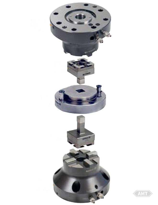
Figure 8-42 Lawn mower blade overload device.
(3) Differential case gear (Figure 8-43).
This new differential case gear is used in the transmission of snow thrower production line with 8.5 horsepower and higher. The new design improves the drive torque output power of the device by accelerating the gear ratio of the pinion and transmission friction plates. The gear can remotely close and activate the differential. The part is pressed into its final shape with a density of 6.8g/cm3. This complex five - surface part has an ultimate tensile strength of not less than 520MPa, transverse rupture strength of 900MPa, yield strength of 620MPa, and fatigue limit of 234MPa. Subsequent machining of the part is limited to quenching and tempering.
(4) Brake arm (Figure 8-44).
This part is used in the zero - radius control device of high - end industrial and residential riding mowers. This innovative powder metallurgy part replaces two assemblies each consisting of six parts, saving 12 parts and related labor and assembly costs. The powder metallurgy lever arm includes a bevel gear and a lever stop block for controlling the hydraulic device. The part is available in left - and right - handed versions and is made of MPIF FC0208 material. The brake arm has a density of 6.7g/cm3;, ultimate tensile strength of 345MPa, hardness of 75 - 100HRB, and excellent wear resistance. The annual production of the part is no less than 200,000 units.
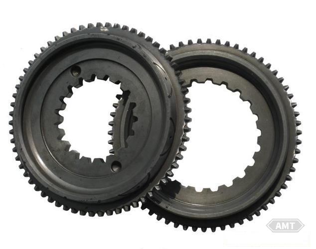
Figure 8-43 The differential case gear.
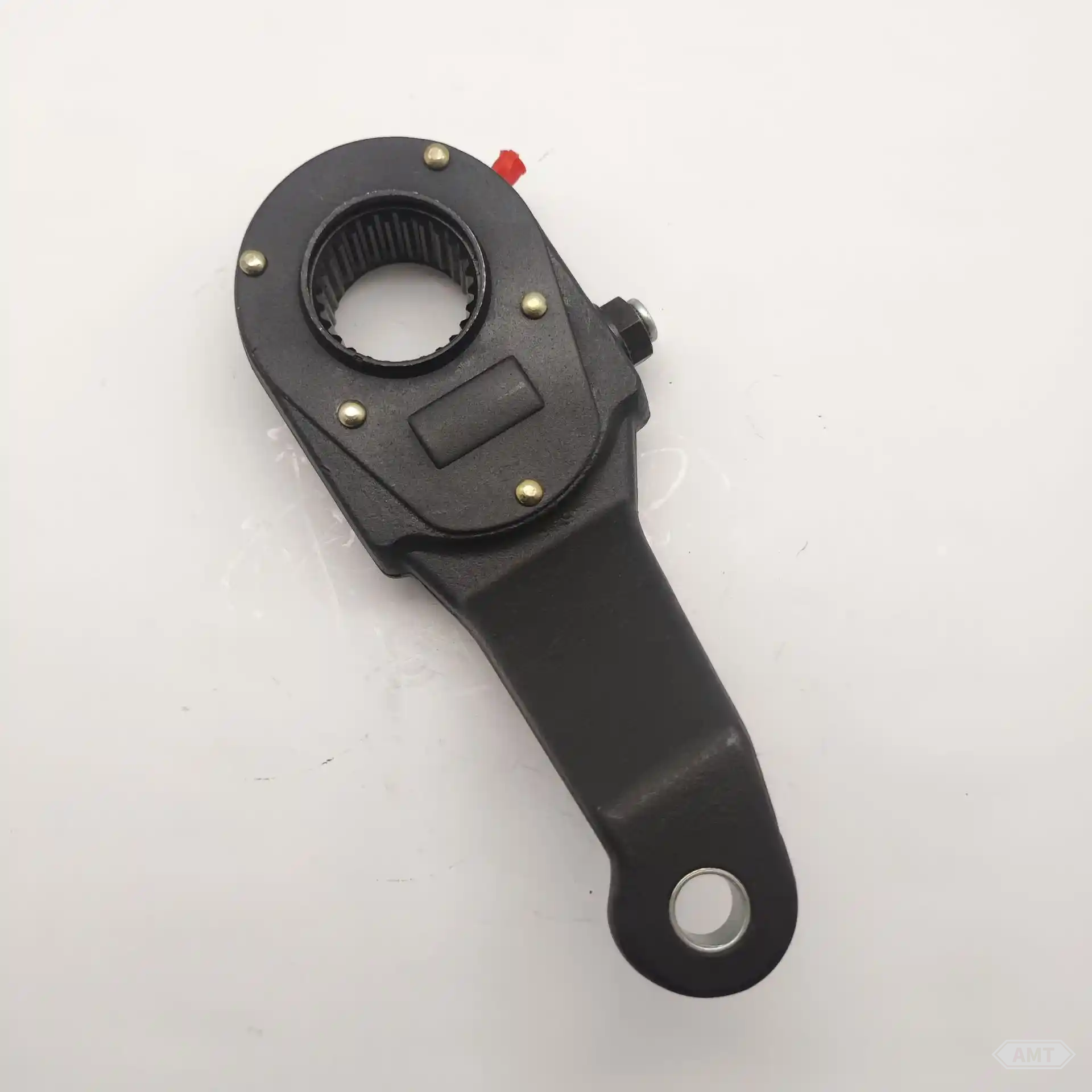
Figure 8-44 The brake arm.

Figure 8-45 The forward/reverse brake assembly.
(5) Forward/reverse brake assembly (Figure 8-45).
These parts are six precision near - net - shape powder metallurgy parts used to assemble the forward/reverse brake assembly in golf cart transmissions. By changing the electrical switch and activating the transmission, it connects to the forward or reverse gear mechanism. The parts generally have a density of 6.9g/cm3. Most parts require heat treatment to achieve an ultimate tensile strength of 830MPa, yield strength of not less than 760MPa, fatigue strength of 300MPa, and hardness of generally 35HRC. The parts do not require machining, with subsequent processing including galvanizing and vacuum oil impregnation. Users estimate that powder metallurgy can reduce production costs by 50% compared to the most competitive manufacturing processes.
Leave your email for more ebooks and prices📫 !
Contact:Fidel
Tel:021-5512-8901
Mobile:19916725893
Email:sales7@atmsh.com
Address:No.398 Guiyang Road Yangpu China