
Date:2025-07-01 Views:0
Table of contents
Oscillating Shaft Servo Cam and Tappet
Cotton Picker Rod Pivot Finger Pin
In the agricultural machinery industry, design engineers consider the design of powder metallurgy parts from the initial design stage. This approach not only helps reduce production costs but also improves part functionality or reliability. This section introduces some typical powder metallurgy parts used in tractors, cotton pickers, seed drills, grain drills, and combine harvesters.
In the agricultural machinery industry, design engineers start considering how to design powder metallurgy parts at the beginning of the design stage, which is beneficial for reducing production costs and improving the functionality or reliability of the parts. In this section, we will introduce some typical powder metallurgy parts used in tractors, cotton pickers, seeders, grain planters, and combine harvesters.
Below, we mainly introduce some typical powder metallurgy structural parts applied in American agricultural machinery and grassland and horticultural machinery, for reference by agricultural machinery and related enterprises in China.
In two-wheel-drive cultivator tractors with mechanical front-wheel-drive boosters, a full hydrostatic steering system is employed, meaning there is no mechanical connection between the steering wheel and the front wheels. The operator controls the high-pressure oil column using a power steering metering pump to steer the tractor. The metering pump actuates the steering valve, which in turn controls the steering motor. In reality, it is the steering motor that directs the tractor's movement.
The power steering metering pump consists of a cover, base, pump body, and two gears, all manufactured using powder metallurgy processes. As shown in Figure 8-1 and Table 8-1, these powder metallurgy parts require minimal machining, primarily grinding and drilling of transverse holes. To prevent leakage, the cover, base, and pump body are impregnated with epoxy resin. As required, the base and pump body undergo nitrogen gas pressure leakage testing, while the gears are subjected to crush testing.
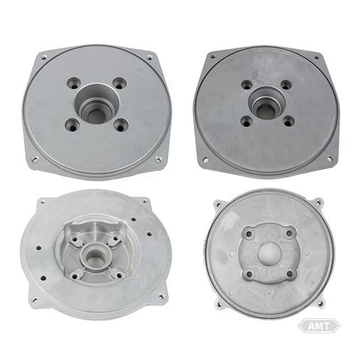
Figure 8-1 Powder metallurgy parts for power steering metering pumps
Table 8-1: Composition and Properties of Powder Metallurgy Parts for Power Steering Metering Pumps
Item | Cover | Base | Pump Body | Gear | Gear |
MPIF Material | FC-0408-P | FC-0408-P | FC-0408-P | FC-0408-P | |
Carbon Content (%) | 0.60~1.00 | 0.60~1.00 | 0.8 | 0.60~1.00 | 0.60~1.00 |
Copper Content (%) | 2.00~6.00 | 2.00~6.00 | 2.0 | 2.00~6.00 | 2.00~6.00 |
Nickel Content (%) | 0.40~0.50 | ||||
Manganese Content (%) | 0.25~0.35 | ||||
Molybdenum Content (%) | 0.55~0.65 | ||||
Iron Content (%) | 91.00① | 91.00① | 91.00① | 91.00① | |
Density① (g/cm3) | 6.4 | 6.4 | 6.4 | 6.4 | 6.4 |
Apparent Hardness | 55HRB | 55HRB | 25HRC | 25HRC | |
Microhardness① (HRC) | 55 | 55 | 55 | ||
Compressive Strength (MPa) | 515 | 515 | 515 | ||
Crushing Strength (kN) | 26.7 | 26.7 | |||
Impregnation | Epoxy Resin | Epoxy Resin | Epoxy Resin | ||
Finished Product Mass (kg) | 1.400 | 1.460 | 0.460 | 0.125 | 0.159 |
Leakage Test | Must Withstand 690kPa | Nitrogen Pressure for 5min Without Leakage |
①Minimum
The three-point hitch, which detects the load and depth of tillage implements, can control the depth embedded in the soil. Alternatively, a sensing device can regulate the draft load of the cultivator tractor. An oscillating shaft servo cam and tappet (Figure 8-2 and Table 8-2) can perform this function. These parts were initially designed as powder metallurgy parts due to their excellent wear resistance and minimal machining requirements.
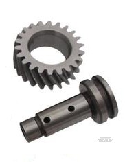
Figure 8-2 Oscillating Shaft Servo Cam and Tappet
Table 8-2: Composition and Mechanical Properties of Oscillating Shaft Servo Cam and Tappet
Item | Cam | Pushrod | Item | Cam | Pushrod |
MPIF Material | FC-0408-P | FC-0408-P | Infiltration Copper | Hole Area to 7.2g/cm3 | |
Carbon Content /% | 0.60~1.00 | 0.60~1.00 | Microhardness /HRC | Cam Surface 52 | 52 |
Copper Content /% | 2.00~6.00 | 2.00~6.00 | Apparent Hardness /HRB | Hole Area 80~100 | |
Iron Content (Minimum) /% | 91.00 | 91.00 | Heat Treatment | Cam Surface Induction Quenching | Quenching and Tempering |
Density (Minimum) (g/cm3) | 6.4 | 6.4 | Finished Product Mass /kg | 0.735 | 0.136 |
The working surface of the cam must be induction hardened to a microhardness of no less than 52HRC. Subsequent operations include drilling transverse holes and tapping. During testing, it was found that the threads in the transverse holes could cause brittle fracture. To address this, copper infiltration was applied to the threaded areas to enhance toughness.
The tappet is made of the same material as the cam but is heat-treated to a hardness of no less than 52HRC.
Powder metallurgy gears are used for oil pump gears to reduce production costs. The oil pump gears in transmissions (Figure 8-3 and Table 8-3) were originally designed as powder metallurgy gears. Initially, the engine's oil pump gears were made of steel but were changed to powder metallurgy gears in 1965. The rated pressure for engine gears is generally 0.4MPa, while that for transmission oil pump gears is 1.38MPa.
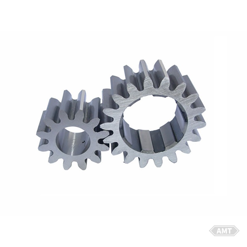
Figure 8-3 Transmission Oil Pump Gear
Table 8-3: Composition and Properties of Transmission Oil Pump Gears
Item | Idler Wheel | Driven Gear | Item | Idler Wheel | Driven Gear |
MPIF Material | FC-0408-P | FC-0408-P | Density (Minimum) (g/cm3) | 6.35 | 6.35 |
Carbon Content /% | 0.60~1.00 | 0.60~1.00 | Microhardness /HRC | 55 | 55 |
Copper Content /% | 2.00~6.00 | 2.00~6.00 | Heat Treatment | Quenching and Tempering | Quenching and Tempering |
Iron Content (Minimum) /% | 91.00 | 91.00 | Finished Product Mass /kg | 0.181 | 0.318 |
Cotton pickers typically utilize various parts for cotton harvesting operations. Although the annual production of cotton pickers is not large, certain parts may be produced in the millions. Two powder metallurgy parts currently used in cotton pickers are the cotton picker rod drive gear and the cotton picker rod pivot finger pin. As shown in Figure 8-4, each four-row cotton picker uses 96 of each of these two parts.
The cotton picker rod drive gear (Figure 8-5 and Table 8-4) drives a rod supporting 20 cotton picker columns. This gear was initially designed as a powder metallurgy gear, with its density increased to 7.2g/cm3 through compaction. After sintering, the gear undergoes heat treatment and quench hardening. Batch parts are inspected using a static load tooth strength test. Induction hardening has been considered for industrial applications, as it allows for a lower overall density (7.1g/cm3). Induction hardening induces compressive stress, compensating for density variations.
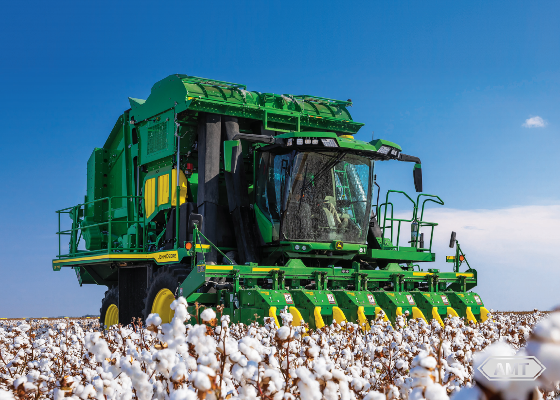
Figure 8-4 Four-Row Cotton Picker
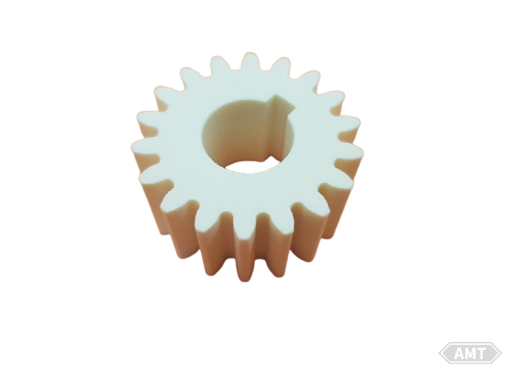
Figure 8-5 Cotton Picker Rod Drive Gear
Table 8-4: Composition and Properties of Cotton Picker Rod Drive Gear
Item | Type 1 | Type 2 |
MPIF Material | FN-0405-T | FL-4605-S |
Carbon Content/% | 0.3~0.6 | 0.35~0.65 |
Nickel Content/% | 3.0~5.5 | 1.80~2.20 |
Molybdenum Content/% | - | 0.30~0.70 |
Manganese Content/% | - | 0.25~0.45 |
Copper Content (Max)/% | 2.0 | 0.50 |
Iron Content/% | 89.9~96.7 | 95.00 (Min) |
Density/(g/cm3) | 7.2~7.6 | 7.1 (Min) |
Apparent Hardness/HRC | 40~52 | 35 (Min) |
Microhardness/HRC | - | 50 (Min) |
Heat Treatment | Quenching and Tempering | Induction Hardening |
Carburizing Depth/mm | - | 0.5 (Min at the root) |
Finished Product Mass/kg | 0.180 | 0.178 |
The cotton picker rod pivot finger pin (Figure 8-6 and Table 8-5) supports the lower end of the cotton picker. The part must be hardened to an apparent hardness of no less than 25HRC (density 7.0g/cm3). For mass-produced parts, a torsion test is used for evaluation.

Figure 8-6 Cotton Picker Rod Pivot Finger Pin
Table 8-5: Composition and Properties of Cotton Picker Rod Pivot Finger Pin
Project | Performance |
MPIF Material | FN-0405-S |
Carbon Content/% | 0.3 ~ 0.6 |
Nickel Content/% | 3.0 ~ 5.5 |
Copper Content (Maximum)/% | 2.0 |
Iron Content (Minimum)/% | 89.9 |
Density (Minimum)/(g/cm3) | 7.0 |
Apparent Hardness (Minimum)/HRC | 25 |
Heat Treatment | Quenched and tempered |
Finished Part Mass/kg | 0.310 |
Modern seed drills not only sow seeds but also perform auxiliary functions. These parts can distribute liquids or dry fertilizers, herbicides, and pesticides. Design efforts have been made to ensure precise control over the quantity of seeds, fertilizers, herbicides, and pesticides dispensed during sowing. Many powder metallurgy parts are used in seed drills; below are some typical ones related to material quantity control.
The seed drill (Table 8-6), featuring a finger-type picker seed metering system as shown in Figure 8-7, was originally designed for grain sowing but is also suitable for sunflower seeds used in candy and snack production. The picker has 12 spring-loaded fingers that continuously open and close around individual seeds. A powder metallurgy cam (Figure 8-8) controls the finger motion. The cam must be wear-resistant as the fingers pressing against it are carburized, quenched, and chromium-plated. The cam is hardened and tempered to an apparent hardness of no less than 58HRA and an average hardness of 60HRA to achieve sufficient wear resistance.
Table 8-6: Composition and Properties of Floating Cam for Finger-Type Picking Mechanism
Item | Performance |
MPIF Material | FN-0208-R |
Carbon Content /% | 0.60~1.00 |
Copper Content /% | 1.90~2.00 |
Nickel Content /% | 1.65~1.90 |
Molybdenum Content /% | 0.50~0.65 |
Iron Content /% | Remainder |
Density (Minimum) (g/cm3) | 6.6 |
Apparent Hardness /HRA | 58 (Minimum), 60 (Average) |
Heat Treatment | Quenching and Tempering |
Finished Product Mass /kg | 0.225 |
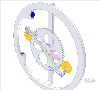
Figure 8-7 Cross-Sectional View of Finger-Type Picking Mechanism
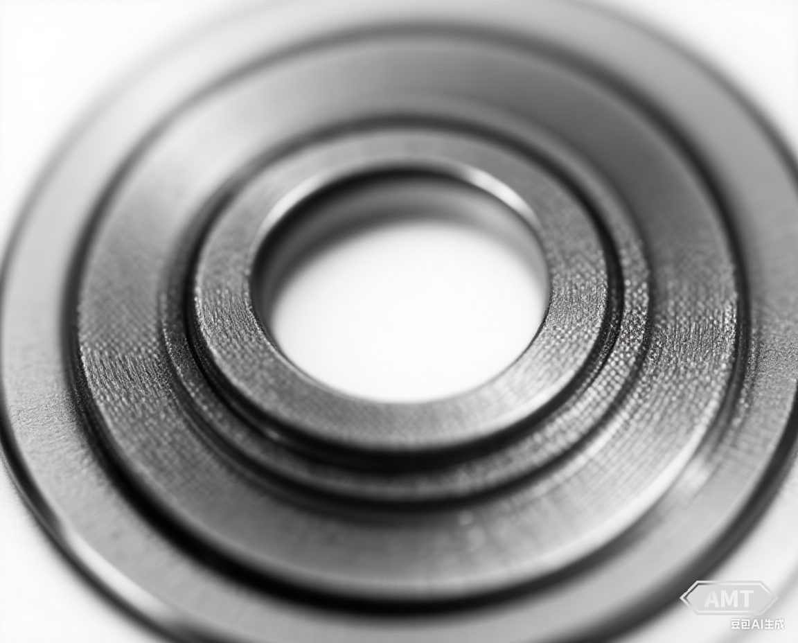
Figure 8-8 Floating Cam for Finger-Type Picking Mechanism
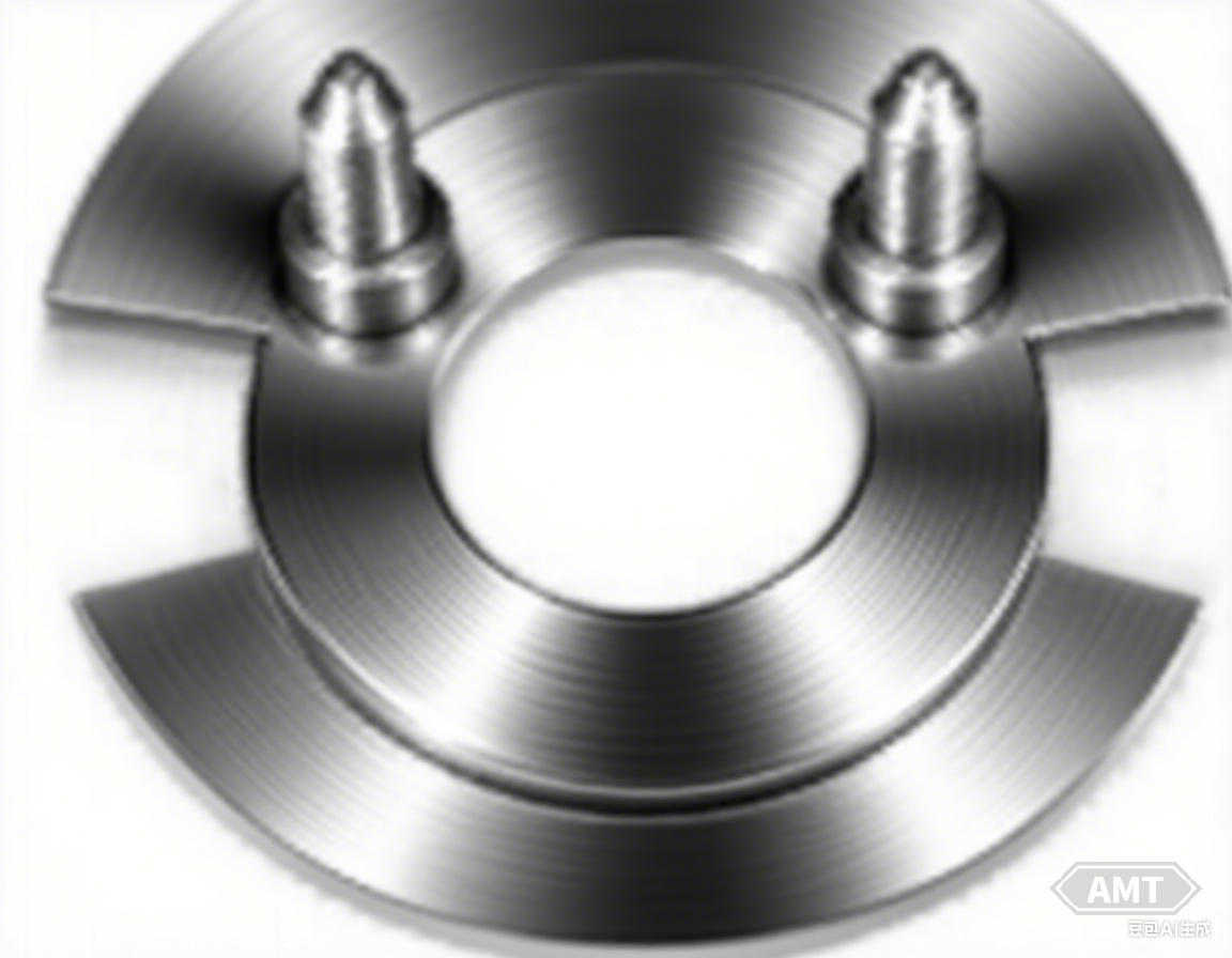
Figure 8-9 Floating Cam Used in Clutch-Less Seed Drill
As shown in Figure 8-9, the floating cam used in a clutch-less seed drill consists of three powder metallurgy parts, two pins, and one cam plate. After compacting the three parts, they are assembled in the green state and sintered together. Technical specifications are detailed in Table 8-7.
Table 8-7: Technical Requirements for Floating Cam
Item | Cam Plate | Pin | Item | Cam Plate | Pin |
Density (g/cm3) | 6.6 | 6.6 | Molybdenum Content/% | 0.5~0.65 | - |
Carbon Content/% | 0.6~1.0 | 0.6~1.0 | Weight/g | 228~232 | 17~18 |
Copper Content/% | 1.9~2.0 | 2.75~3.0 | Total Component Mass/g | 263~267 | - |
Nickel Content/% | 1.65~1.9 | 1.0~1.2 | Hardness/HRC | 60 (File Test) |
The twin sprocket assembly (Figure 8-10 and Table 8-8) is a component made by connecting two powder metallurgy sprockets with a pin. This allows for different transmission ratios using a pair of single-piece sprockets, eliminating the need to manufacture a set of twin sprockets for each required ratio. The pin-connected powder metallurgy gear assembly replaces parts previously made by machining and welding, saving significant costs. The twin sprocket is mounted on the shaft of the fixed seed metering device. The drive chain engages one of the sprockets in the twin assembly, causing the assembly to rotate and drive the seed metering device.
Table 8-8: Composition and Properties of Twin Sprocket Assembly
Item | 11-Tooth Sprocket | 19-Tooth Sprocket |
MPIF Material | F-0005-S | F-0005-S |
Carbon Content/% | 0.26~0.60 | 0.26~0.60 |
Iron Content (Minimum) /% | 97.40 | 97.40 |
Density/(g/cm3) | 6.9~7.3 | 6.9~7.3 |
Finished Product Mass/kg | 0.227 | 0.680 |
Additional Requirements | Sprocket connected with a stake |
The sprocket assembly (Figure 8-11 and Table 8-9) is manufactured by brazing the compacted green sprocket onto a metal plate baffle during sintering. It is installed on the herbicide/pesticide metering device of the seed drill. Figure 8-10 illustrates the twin sprocket assembly.
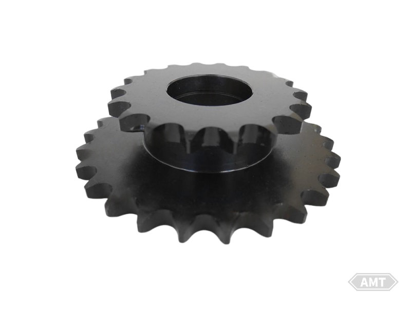
Figure 8-10 Twin Sprocket Assembly
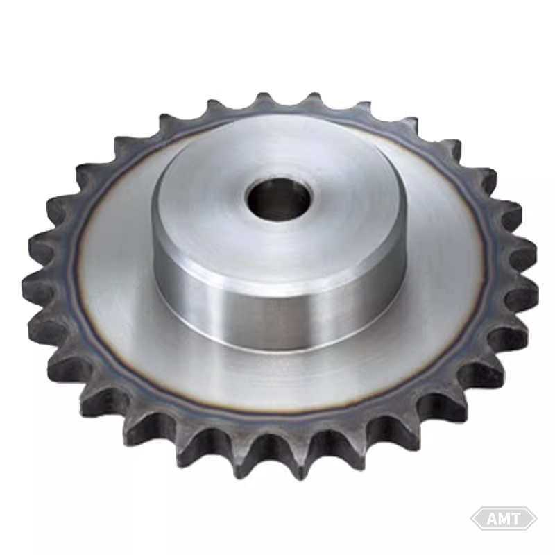
Figure 8-11 Sprocket Assembly (Sprocket Plus Baffle)
Table 8-9: Composition and Properties of Sprocket Assembly (Sprocket Plus Baffle)
Item | Sprocket | Steel Plate |
MPIF Material | FC-0208-P | Steel Plate |
Carbon Content/% | 0.60~1.00 | |
Copper Content/% | 1.00~2.50 | |
Iron Content (Minimum) /% | 94.5 | |
Density/(g/cm3) | 6.1~6.5 | |
Finished Product Mass/kg | 0.091 |
Note: Assembled before sintering and brazed together during sintering.
This powder metallurgy part is manufactured by assembling two compacted green powder metallurgy parts and sintering them into an integrated component (Figure 8-12 and Table 8-10). It is used to tension the chain via a nylon idler wheel, thereby driving the aforementioned twin sprocket assembly.
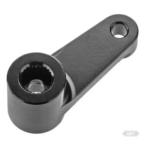
Figure 8-12 Idler Arm
Table 8-10: Composition and Properties of Idler Arm
Item | Arm | Handle |
MPIF Material | F-0008-P | FC-0408-P |
Carbon Content/% | 0.61~1.00 | 0.60~1.00 |
Copper Content/% | - | 2.00~6.00 |
Iron Content (Minimum)/% | 97.00 | 91.00 |
Density/(g/cm3) | 6.1~6.5 | 6.1~6.4 |
Heat Treatment | Sintering followed by steam treatment | - |
Finished Product Mass/kg | 0.132 | 0.132 |
As shown in Figure 8-14, the feeder roller and closing device are located within the feed chamber. The trough-type feed chamber controls the amount of seeds allocated to the grain drill and can be used to sow almost any type of seed.
During sowing operations, the feeder roller rotates while the closing device remains stationary. The depth to which the closing device extends into the feed chamber determines the amount of seeds dispensed.
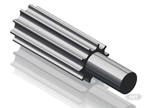
Figure 8-13 Feeder Roller and Closing Device
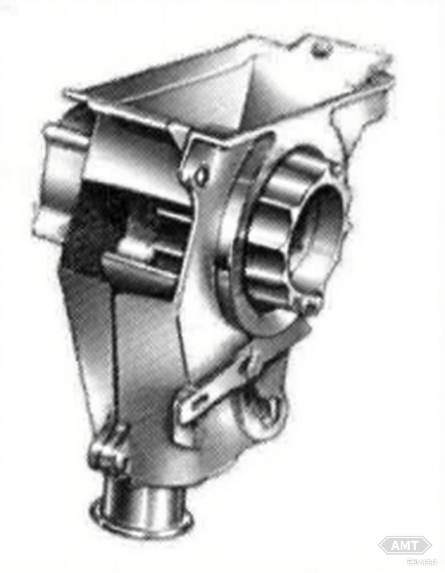
Figure 8-14 Feeder Roller and Closing Device in the Feed Chamber
Item | Feeding Roller | Closure Device | |
Groove | Rod | ||
MPIF Material | F-0005-N | FC-0400-N | FC-0208-P |
Carbon Content/% | 0.26~0.60 | 0.30 (Max) | 0.60~1.00 |
Copper Content/% | - | 2.00~6.00 | 2.00~6.00 |
Iron Content (Minimum)/% | 97.40 | 90.70 | 91.00 |
Density/(g/cm3) | 5.7~6.1 | 5.8~6.2 | 6.1~6.5 |
Apparent Hardness (Minimum)/HRA | 55① | - | - |
Heat Treatment | Carburizing and Nitriding | Carburizing | Steam Treatment |
Additional Requirements | - | - | Oil Impregnation |
Finished Product Mass/kg | 0.455 | 0.455 | 0.255 |
The planetary gear assembly for the grain drill was initially designed as a powder metallurgy part.
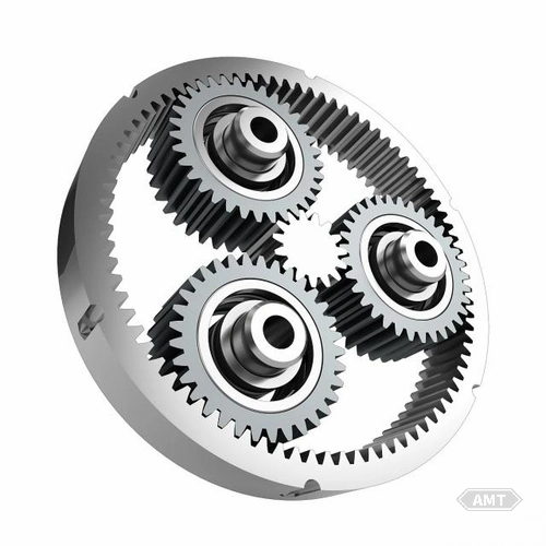
Figure 8-15 Planetary Gear Assembly
Before the development of the powder metallurgy planetary gear assembly, a sliding gate valve was used to regulate the efficiency of fertilizer application by controlling the gravity flow of fertilizer. This method had several issues, such as fertilizer piling up in front of the sliding gate, and variations in land slope and moisture affecting the characteristics of gravity flow.
Table 8-12: Composition and Properties of Planetary Gear Assembly
Item | Internal Gear | Planetary Gear | Center Gear |
MPIF Material | FC-0208-P | FC-0208-P | FC-0208-P |
Carbon Content/% | 0.60~1.00 | 0.60~1.00 | 0.60~1.00 |
Copper Content/% | 1.00~2.50 | 1.00~2.50 | 1.00~2.50 |
Iron Content (Minimum)/% | 94.50 | 94.50 | 94.50 |
Density/(g/cm3) | 6.1~6.5 | 6.1 (Minimum) | 6.1~6.5 |
Tensile Strength (Minimum)/MPa | 345 | 345 | 345 |
Finished Product Mass/kg | 0.509 | 0.100 | 0.055 |
The planetary gear assembly is part of the system's improvement, enabling feeding of fertilizer using a follower feed wheel. The feed wheel is mounted on the feed shaft, and the fertilizer application rate can be adjusted by changing the speed of the feed shaft.
Combine harvesters cut, thresh, and temporarily store grain. Some powder metallurgy parts used in combine harvesters include cams, gears, and hydraulic circuit boards.
The inner/outer 45° cams (Figure 8-16 and Table 8-13) function as torque-sensing elements to adjust the tension of the V-belt driving the reversible, variable-speed feeder housing. They undergo carbonitriding to enhance the wear resistance of the cam acting surfaces and the inner and outer diameters. The outer cam also serves as a bushing for half of the pulley, making this treatment necessary. After heat treatment, the inner and outer diameters of the cam are precision ground.
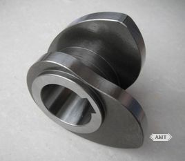
Figure 8-16 Inner/Outer 45° Cams
Table 8-13: Composition and Properties of Inner/Outer 45° Cams
Item | Internal Cam | External Cam |
MPIF Material | FC-0205-R① | FC-0205-R① |
Carbon Content/% | 0.3~0.6 | 0.3~0.6 |
Nickel Content/% | 1.0~3.0 | 1.0~3.0 |
Copper Content (Maximum)/% | 2.5 | 2.5 |
Iron Content/% | 91.9~98.7 | 91.9~98.7 |
Heat Treatment | Carburizing and Nitriding | Carburizing and Nitriding |
Carburizing Depth/mm | 0.51 after grinding | 0.51 after grinding |
Finished Product Mass/kg | 1.415 | 2.041 |
The density of the cams is 6.4 ~ 6.8g/cm3.
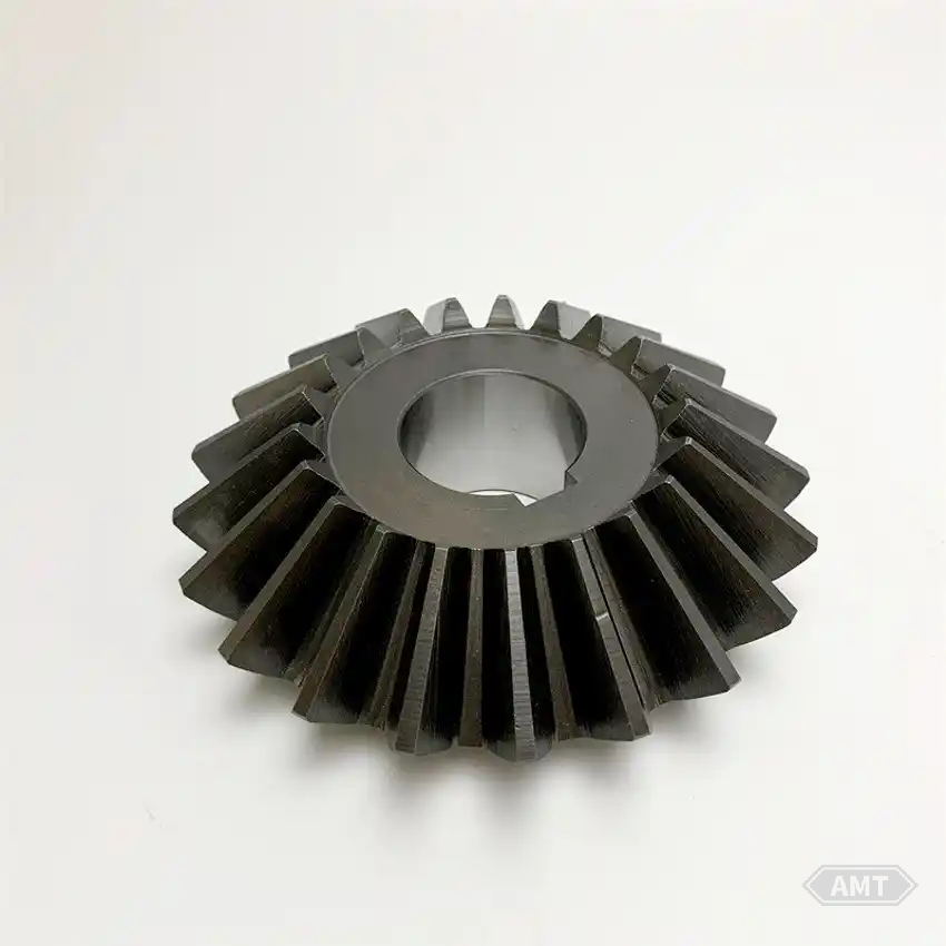
Figure 8-17 Helical Bevel Gear
These helical bevel gears (Figure 8-17 and Table 8-14) are used in pairs to transmit power from the drive shaft to a 90° helical propeller. The helical propeller extends almost the entire length of the combine harvester, conveying threshed grains to the front of the cleaning system.
In four-wheel-drive combine harvesters, two wheels are driven by hydraulic cam lobe motors. A large powder metallurgy part is centrally located within the motor, serving as a hydraulic circuit board (Figure 8-18 and Table 8-15). Weighing approximately 15kg, this circuit board is characterized by 30 radial oil passages.
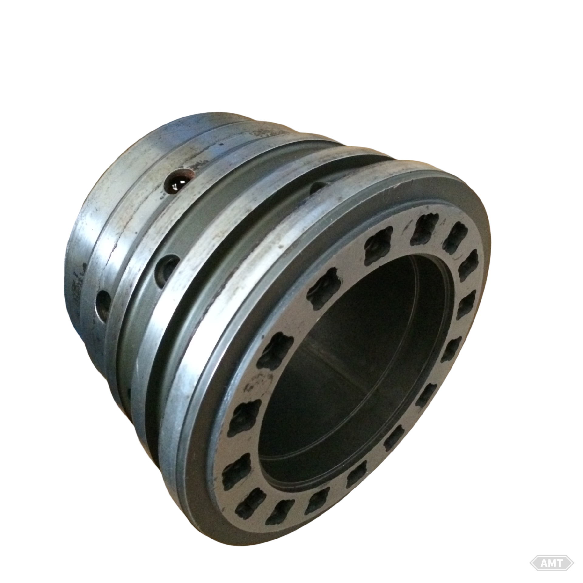
Figure 8-18 Hydraulic Wheel Motor Circuit Board
The circuit board is designed as a powder metallurgy part due to the high machining costs associated with other manufacturing processes. Even with powder metallurgy, it is challenging to produce. The complex mold requires a compound-action upper punch, two lower punches, and a mandrel with a core pin to form the 30 radial oil passages.
Table 8-14: Composition and Properties of Helical Bevel Gears
Table 8-15: Composition and Properties of Hydraulic Wheel Motor Circuit Board
Item | Performance |
MPIF Material | FX-2008-T |
Carbon Content/% | 0.61~1.00 |
Copper Content/% | 15.00~25.00 |
Iron Content/% | 69.00~84.39 |
Infiltration | Copper |
Density/(g/cm3) | 7.1~7.6 |
Heat Treatment | Carburizing and Nitriding |
Particle Hardness (Minimum)/HRC | 58 |
Apparent Hardness (Minimum)/HRB | 95 |
Finished Product Mass/kg | 0.340 |
The circuit board is compacted on an 8.9MN press. To ensure seal integrity under high pressure, copper infiltration is performed during sintering, which also provides lubricity during operation. The final density of the part is 7.1 ~ 7.6g/cm3.
Before use, the circuit board requires some machining, limited to turning the inner and outer diameters and drilling holes. Given the complex shape of the part, significant production cost savings are achieved even for moderate quantities (5,000 ~ 10,000 pieces).
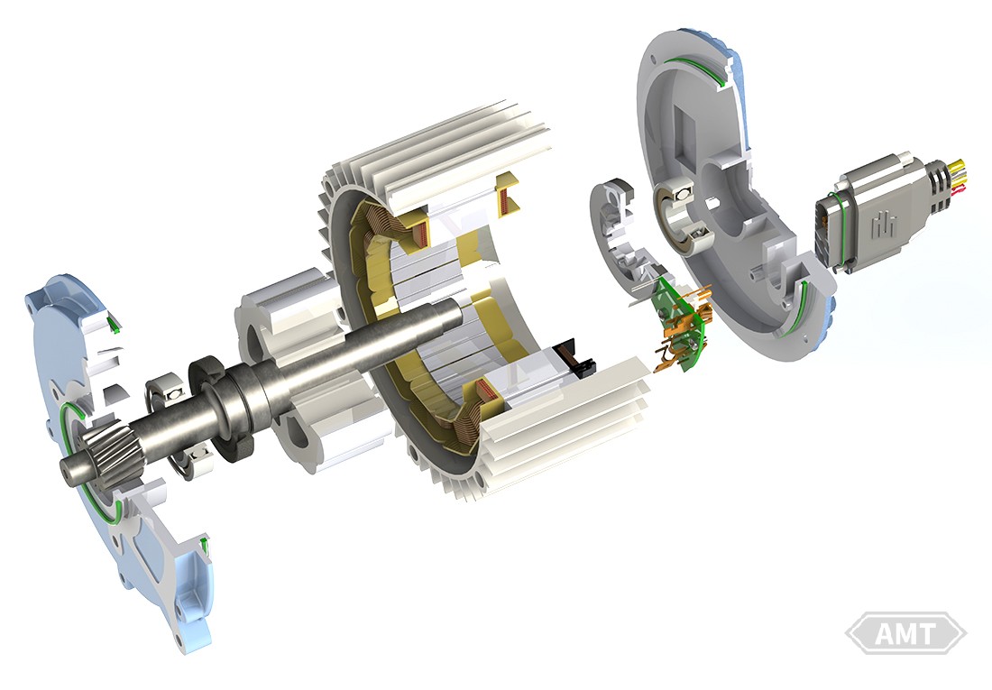
Figure 8-19 Partial exploded view of cam convex angle hydraulic wheel motor
Leave your email for more ebooks and prices📫 !
Contact:Fidel
Tel:021-5512-8901
Mobile:19916725893
Email:sales7@atmsh.com
Address:No.398 Guiyang Road Yangpu China