
Date:2025-06-20 Views:1004
Table of contents
Powder Metallurgy Components in Manual Transmission Synchronizer Systems
Powder Metallurgy Synchronizer Hubs
Powder Metallurgy Synchronizer Lock Rings
Manual transmissions in both passenger cars and trucks are equipped with synchronizer devices to ensure smooth gear operation and convenient shifting. In addition to shafts and bearings, a synchronizer device consists of five key components:
1.The synchronizer hub mounted on the drive shaft;
2.The sliding sleeve that transfers torque from the shaft/hub assembly;
3.The clutch gear and its firmly attached clutch cone, with the clutch cone welded or otherwise fixed to the clutch gear;
4.The freely rotating transmission gear, which, when the sliding sleeve engages with the clutch gear, locks the "free" rotating transmission gear onto the drive shaft and transfers torque to the intermediate shaft transmission gear rigidly fixed on the output shaft;
5.The synchronizer lock ring, which, before the sliding sleeve engages with the clutch gear, connects with the clutch cone to synchronize the rotational speed between the drive shaft and the output shaft.
For the normal operation of the transmission and the comfort of the driver during gear shifting, the performance of the synchronizer device is crucial. Therefore, all components of the synchronizer system must meet the requirements of reliability and comfort. Over the years, powder metallurgy synchronizer hubs have always had an advantage, and in the past decade (1997~2007), the production volume of powder metallurgy hubs has been growing. In today's synchronizer hub market, it occupies about 65% of the share. In addition, powder metallurgy components such as synchronizer lock rings and clutch cones account for 15% of the market share. The sliding sleeve and gear have always been produced by forged steel. Given the main advantages of powder metallurgy processes, such as the ability to form into the final shape and reduce production costs, these are also applicable to the sliding sleeve and gear. Therefore, the development of these new applications using powder metallurgy processes is full of opportunities.
In the field of manual transmission components, the difficulty in producing powder metallurgy components lies in the need to further develop powder metallurgy materials and production processes while maintaining the traditional advantages of powder metallurgy processes. Additionally, it is necessary to provide products with appropriate performance for the automotive market. In this sense, this book describes the current and future applications of powder metallurgy components in synchronizer devices and briefly reviews some of the recent development focuses.
In the past, powder metallurgy synchronizer hubs have always occupied a significant market share and are the most widely used powder metallurgy components in manual transmissions, mainly due to their high cost-effectiveness. If the performance of hubs for high-torque applications can be significantly improved, powder metallurgy hubs will have the potential for further growth in applications. The author believes that the prerequisite for this progress is the development of powder metallurgy steels with excellent mechanical properties. In addition to reducing porosity, optimizing the alloy composition related to permeability is a key factor in effectively strengthening powder metallurgy steel.
The most promising development for high-performance synchronizer hubs is Cr-alloyed powder metallurgy steel. The characteristics of mass-produced pre-alloyed Fe(Cr, Mo) powders are completely uniform microstructures. However, the powder metallurgy steel currently used in synchronizer hub production is mainly diffusion-alloyed, and its microstructure inevitably contains soft phases such as Ni-stabilized austenite, ferrite, or pearlite. This multiphase nature can deteriorate the static strength, hardness, and fatigue performance of the components.
Synchronizer hubs are essentially loaded under alternating torque and the effect of severe notches in front of the internal spline and synchronizer slot. Moreover, the teeth are prone to wear, especially when axial forces press them against gears or bearings. Therefore, the need teeth to have excellent fatigue strength and surface hardness. Figure 4-19 compares the mechanical properties of various high-strength powder metallurgy steels. Clearly, chromium steel is expanding into the realm of possessing excellent fatigue strength and hardness properties. Since Cr and Mo have excellent permeability effects, it is easy to form a uniform microstructure between full bainite and full martensite, provided that the production process is appropriate. In addition, (Cr, Mo) powder metallurgy steel also has excellent strength and hardness, as well as appropriate toughness and ductility. Figure 4-19 shows that the hardness and fatigue strength of the (Cr, Mo) alloyed SIRON®; steel grade are superior to the performance of Fe-(Mo)-Ni-Cu mixed alloy steel. In particular, the axial fatigue strength (σ·50%) of Fe-(Cr, Mo)-based materials exceeds 240 MPa. As shown in Figure 4-19, although the carbon content of Fe-(Cr, Mo) steel is lower than that of the two Fe-(Mo)-Ni-Cu mixed alloy steels, its performance (fatigue resistance) is better than that of Fe-(Mo)-Ni-Cu mixed alloy steel. When the performance of a component requires both static strength and fatigue performance, this combination of properties is particularly important.
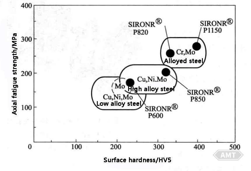
Figure 4-19 Comparison of the "Fatigue Strength/Hardness Domain" Achievable by Various Powder Metallurgy Steel Series with a Density Level of 6.8~7.2 g/cm3;
The numerical designation of the SIRON®; powder metallurgy steel grade for synchronizer hubs indicates tensile strength (MPa).
When changing gears, the gear synchronizing system must ensure that the shaft and the gear to be meshed rotate synchronously. The synchronization process requires the gear to accelerate or decelerate to overcome the inertia of the transmission. As previously mentioned, this is achieved using a synchronizer lock ring and a conical friction clutch. The synchronizing system also serves as a flexible locking mechanism to prevent "direct shifting" before rate synchronization. Most low-torque manual transmissions still use threaded brass synchronizer lock rings. Due to increased requirements for inertia and wear, high-torque transmissions require a synchronizer lock ring composed of a high-strength wear-resistant steel body and a specially formulated friction material bonded to its conical cross-section. Figure 4-20 shows the structure of the friction lining on the conical cross-section of a powder metallurgy steel synchronizer lock ring.
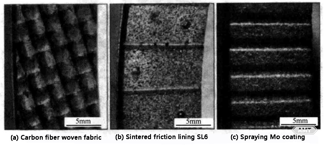
Figure 4-20 Structure of the Friction Lining on the Conical Cross-Section of a Powder Metallurgy Synchronizer Lock Ring
(a) Carbon fiber weave
(b) Sintered friction lining SL6
(c) Sprayed Mo coating
The three types of friction linings were evaluated through load grading and durability tests:
Continuous fiber woven carbon weave;
Sintered friction lining SL6;
Sprayed Mo coating.
Mo coatings and sintered friction linings are standard friction materials for powder metallurgy synchronizer lock rings. Carbon fiber weaves may improve oil compatibility and are gradually being used to enhance the performance of the friction components in synchronizer systems, having recently gained a significant market share. All friction materials must be combined with the synchronizer lock ring, which is manufactured using advanced powder metallurgy processes from PMG powder metallurgy steel (SIRONP380) and then subjected to plasma nitriding. The carbon lining is bonded to the ring body with a high-temperature curing adhesive, the sintered friction lining SL6 is fixed to the synchronizer lock ring by capacitor discharge welding, and the Mo coating is sprayed onto the cross-section of the ring body using a Mo wire flame spray. As shown in Figure 4-20, these are the macroscopic structures of the three linings. The friction performance of these three friction layers is evaluated using the synchronizer test bench shown in Figure 4-21.
The ZF/FZG-SSP180 test bench developed by the Gear Research Center (FZG) of Munich University is a testing device for evaluating the friction and wear performance of friction materials in synchronizing systems under different loads. The load grading includes systematic changes in pressure (P) and rotational speed difference (△n) through axial force (F). The test results for the sintered friction lining SL6 are shown in Figure 4-22. Under a constant pressure of 5 MPa and a constant rotational speed difference of △n = 1600 r/min, the durability performance of the synchronizer system, that is, the long-term friction and wear characteristics, was studied for up to 10^6 cycles. In each gear shifting cycle, the friction torque as a function of time is measured under the predetermined pressure, and it is easy to evaluate the minimum friction coefficient umin and the average uavg, as well as the synchronization time. For a rapid evaluation of friction performance under different loads, the "p-n-load-grading" test is a suitable method. For more details on this testing method, refer to the relevant literature.
All three friction materials successfully passed the short-term load grading test. However, only the SL6 lining withstood the 10^6-cycle shift durability test, while the Mo coating and carbon weave failed prematurely at 25,000 and 55,000 cycles, respectively. The conclusions are as follows:
1.The carbon weave has the highest friction coefficient, μ>0.12, with applicable wear resistance but tends to exhibit micro-vibration wear under high pressure. It is suitable for large rotational speed differences and short-term synchronization.
2.The Mo coating has a moderate friction coefficient of 0.10 < μ < 0.12, with significant wear and a clear tendency toward micro-vibration wear under high pressure. It is suitable for low and medium rotational speed differences.
3.The sintered friction lining has a friction coefficient similar to the Mo coating, 0.10 < μ < 0.12, but has the best wear resistance among all friction materials. Its performance is optimal under medium to high pressure and medium rotational speed differences.
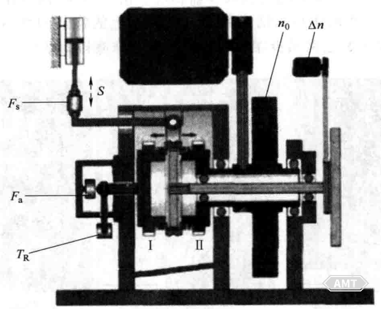
Figure 4-21 Synchronizer Test Bench at Munich University of Technology (ZF/FZG-SSP180)
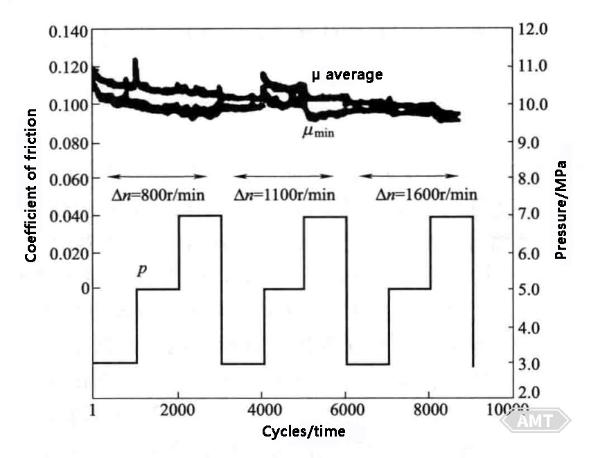
Figure 4-22 Test Results for Sintered Friction Lining SL6
When the driver moves the gearshift lever, the shift fork causes the sliding sleeve to slide axially toward the clutch gear/transmission gear assembly, as shown in Figures 4-18 and 4-23. When the sleeve engages with the clutch gear, the torque flow begins to pass through the system. The geometric shape of the internal spline of the sleeve is very complex, including a tapered shift control rod limiter (Figure 4-24), which prevents the sleeve from accidentally disengaging from the clutch gear during operation. This complex geometric shape is the reason why sliding sleeves have been entirely produced by machining forged steel followed by surface hardening up to 2007.
In 2006, PMG pioneered the mass production of powder metallurgy sliding sleeves for manual transmissions. A complex multi-process production method is used, with compaction and sintering followed by repressing to ensure sufficient density at the top of the internal spline teeth. If the density at the top of the internal spline teeth is insufficient, severe wear will occur when they come into contact with the top of the clutch gear teeth. In such cases, if synchronization fails, the two parts rotating at different speeds will collide with each other, causing severe wear on both sets of teeth and resulting in a clicking noise. After increasing the tooth density, the shift slot and the internal spline shift control rod limiter are machined by turning and milling, respectively. Subsequently, the part undergoes surface hardening and precision machining. Figure 4-24 shows the PMG mass-produced powder metallurgy sliding sleeve. Rigorous testing has been conducted to evaluate its functionality during operation, particularly to inspect the wear resistance of the teeth. Figure 4-25 shows the powder metallurgy sleeve before and after 3×10⁶ shift cycles, with almost no visible wear on the tooth tops. Figure 4-26 compares the tooth profiles of the powder metallurgy sleeve and the conventional forged steel sleeve after 3×10⁶ shift cycles.
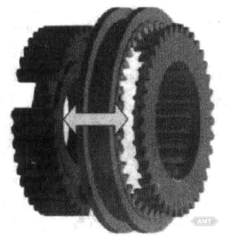
Figure 4-23 Synchronizer Hub, Sliding Sleeve, and Clutch Gear Assembly (Left to Right)
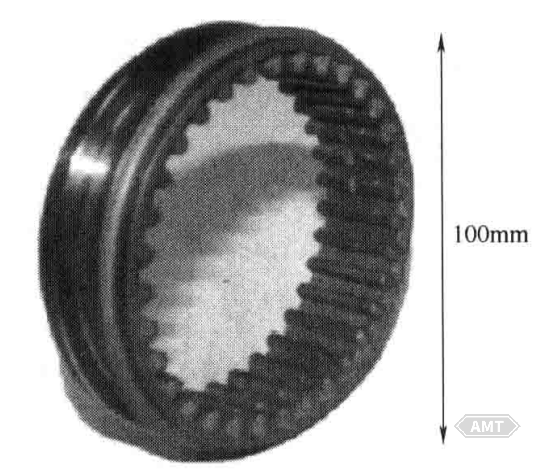
Figure 4-24 PMG Mass-Produced Powder Metallurgy Sliding Sleeve
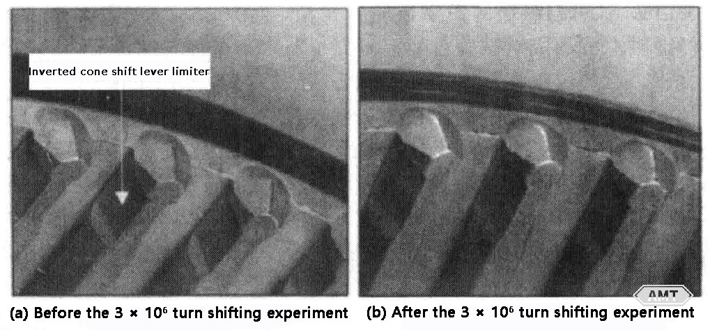
Figure 4-25 Powder Metallurgy Sleeve Before and After 3×10⁶ Shift Cycles
The results indicate that the wear resistance of the repressed powder metallurgy sleeve is comparable to that of surface-hardened forged steel. The applicability of the powder metallurgy sleeve is further confirmed by misuse testing. Under intentional top-to-top contact between the sliding sleeve and the clutch gear, the wear of the powder metallurgy sleeve is similar to or less than that of the forged steel sleeve. The shifting performance, synchronizing performance, and fatigue strength of the powder metallurgy sleeve are comparable to those of conventional forged steel sliding sleeves. Therefore, all test results are positive compared to conventionally produced forged steel sliding sleeves.
Gears are key structural components in manual transmissions. Typically, gears experience pulse stresses during meshing, with stress peaks occurring near the gear surface. Therefore, gears primarily require high strength and wear resistance on the surface or near-surface areas. If the geometric shape and/or assembly of the gear are not precise, it may reduce the gear's service life and load capacity, and increase noise. Hence, the quality requirements for transmission gears are generally high, usually exceeding DIN7 standards. In addition to requirements for strength and noise, there are increased demands for improved economic and performance characteristics. Since the load on gears generates high stresses on the surface or near-surface areas, it is not necessary for the entire component to achieve full density. Selective surface densification is suitable for such load conditions. This process creates a dense layer on the gear surface, with near-zero porosity on the surface and a core porosity of approximately 10% (by volume). In recent years, PMG has developed the DensiForm process, which selectively increases the surface density of sintered gears while maintaining core porosity, thereby forming a fully dense surface layer with a depth of 0.5~1.0 mm (see Figure 4-27). This book examines the current 4th gear of a 5-speed front-wheel-drive manual transmission, as shown in Figure 4-28. The gear has 39 teeth, a helix angle of 33;, and a module of 1.8 mm. The powder metallurgy gear is produced using the powder metallurgy process and subsequently subjected to DensiForm processing and surface hardening.
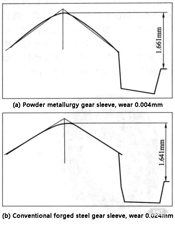
Figure 4-26 Comparison of the tooth top profile between powder metallurgy gear sleeve and conventional forged steel gear sleeve after 3 × 10⁶ cycles of gear shifting
Finally, the gear is ground to a quality higher than DIN7, with a surface roughness Ra < 1.8 μm, comparable to the reference forged steel gear. The production process details can be found in the relevant literature. The load capacity of the powder metallurgy gear and the reference gear was studied on a 3-shaft assembly pair test bench at RWTH Aachen University, with detailed results summarized in Figure 4-28. It is evident that the load capacity of the powder metallurgy gear processed with the DensiForm process falls within the load range of the conventional forged steel gear. Specifically, the bending fatigue strength of the gear root at a 50% survival rate is 675 MPa, comparable to the 750 MPa of the forged steel gear, indicating that the surface-densified powder metallurgy gear's load capacity is approximately 90% of the conventional forged steel gear. Under an applied torque of 340 N·m (equivalent to a gear root stress of 685 MPa), both gears failed due to root fracture between 10×106 and 50×106 cycles (see Figure 4-28), yet no damage or pitting was observed on the gear flanks. Consequently, the performance of the powder metallurgy gear is fully suitable for current transmissions.
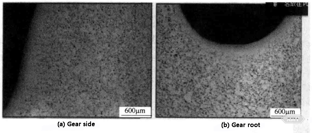
Figure 4-27 Typical Micrographs of Gear Surfaces Processed with the DensiForm Process
The components of the manual transmission synchronizer module are development targets for the powder metallurgy industry, and these components may contribute to the rapid growth of the powder metallurgy parts industry in the coming years. This growth is based on advancements in material properties, production processes, and the applicability of new components. This book's research indicates that in recent years, the overall and surface properties of powder metallurgy steels and functional materials (such as friction layers) have improved. These advancements have been achieved through the use of advanced production equipment and processes, such as furnaces for sintering Cr-alloyed steels or selective surface densification processes like DensiForm. The recognition of new powder metallurgy components, including sliding sleeves and load gears, has opened up new markets for powder metallurgy processes in transmissions.
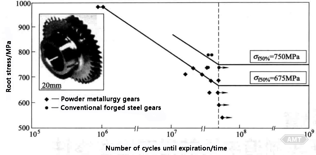
Figure 4-28 S/N (Wohler) Curves for Gears Determined on a Pairwise Gear Test Bench
Leave your email for more ebooks and prices📫 !
Contact:Fidel
Tel:021-5512-8901
Mobile:19916725893
Email:sales7@atmsh.com
Address:No.398 Guiyang Road Yangpu China