
Date:2025-07-14 Views:1003
Modifying the Gear Tooth Shape
Modifying the Production Process
Selecting Compatible Materials
Gear pumps are the most commonly used type of hydraulic components, often serving as pumps and motors. There are two types of powder metallurgy parts in gear pumps: one is the gear; the other is the floating end plate, which is designed for high efficiency, as shown in Figure 9-3. The critical dimensions of gears are length, concentricity, hole size, parallelism, and perpendicularity to the hole. These dimensions are achieved through subsequent machining. When producing gears using powder metallurgy processes, both lead and involute shapes are employed. The key dimensions of wear-resistant plates are sealing diameter, flatness, and seal groove.
In gear pumps used for automotive engine lubrication and automatic transmission low-pressure applications, powder metallurgy parts are typically made of Fe-C or Fe-Cu-C materials with a density of 6.0 to 6.8 g/cm3. In gear pumps operating at pressures above 6.90 to 20.7 MPa, powder metallurgy parts are made of Fe-Ni materials alloyed with molybdenum and manganese, with a density of 7.1 to 7.6 g/cm3. The addition of alloy elements is aimed at improving the heat treatment properties of the material, as shown in Table 9-2.
Figure 9-3 Gears and gear assemblies (including housing and flexible drive plates)
Table 9-2 Classification of Powder Metallurgy Gear Pumps by Material Properties
Application Scenario | Material Used |
Output pressure less than 0.7MPa and light load | Sintered state of FC-0208 material, 5.8~6.2g/cm3 |
Output pressure less than 7MPa, but subjected to high vibration and heavy loads - quenching and hardening by heat treatment | FC-0208 or FN-0106 material, 6.4~6.8g/cm3 |
Medium voltage (7~8.75MPa) for a short time - quenching and hardening by heat treatment | FC-0208 material, 6.2~6.5g/cm3 |
General hydraulic pump for continuous operation with pressure below 10.5MPa | Heat treated state of FN-0106 material, 6.8~7.1g/cm3 |
General hydraulic pump for continuous operation with pressure below 17.5MPa | Heat treated state of 4630 material, 7.2~7.6g/cm3 |
When the operating pressure of the pump exceeds 14 MPa and higher, the transmitted power becomes more critical, with increased shaft size and higher stress. A common practice is to machine the keyway ends into large-radius fillets. Practice has shown that semi-circular keyways can reduce the failure rate of gears under higher pressures. Creating semi-circular keyways using powder metallurgy processes is either easy or cost-effective.
For powder metallurgy gear pumps used in the automotive industry, the efficiency-to-cost ratio is a key factor.
One method to improve gear pump efficiency is to optimize the external gear tooth profile. To study the impact of tooth profile on gear pump efficiency, existing 7-tooth external gear pumps with involute tooth profiles were compared with 7-tooth and 9-tooth gears with cycloid tooth profiles. The gear samples with different tooth profiles and numbers are shown in Figure 9-4. The samples were made from wear-resistant aluminum alloys and the steel alloys currently used in mass production.
Tests were conducted on these gears with different tooth profiles on a pump test rig under various temperatures, pressure levels, and rotational speeds. A standard test procedure was developed to simulate engine operating conditions, including short-term durability tests at room temperature oil and 500 r/min, followed by additional tests at high oil temperature (80℃), and finally long-term durability tests at 2,000 r/min. The volumetric efficiency, torque, and noise levels were measured at six pressure levels between 0.1 and 0.6 kPa.
Figure 9-5 shows the torque characteristics of gear pumps made from a single material at critical operating points (idle speed of 500 r/min and oil temperature of 80℃). It is evident from Figure 9-5 that the mechanical efficiency of the involute tooth profile is the lowest across all tested pressures, resulting in the highest torque. Volumetric efficiency and air noise measurements also clearly indicate the same trend. These research results are presented in Table 9-3.
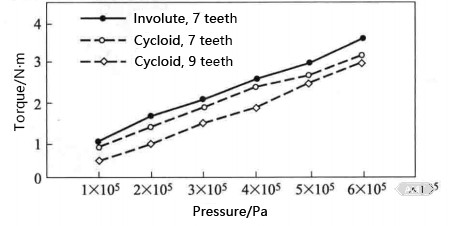
Figure 9-5 Torque characteristics of gear pumps with different tooth shapes
Table 9-3 Results of Oil Pump Tests
Item | Involute (7 Teeth) | Cycloid (7 Teeth) | Cycloid (9 Teeth) |
Volumetric Efficiency/% | 24.1 | 24.4 | 28.6 |
Torque/N·m | 3.5 | 3.1 | 2.9 |
Noise Level/dB | 83.5 | 82.0 | 80.0 |
It can be concluded that modifying the pump design from the current 7-tooth involute tooth profile to a 9-tooth cycloid tooth profile can enhance pump performance. An important benefit of this tooth profile optimization is that it allows for the design of smaller pumps with the same volumetric flow rate.
In addition to improving the tooth profile, the production process of pump gears can be refined to optimize pump efficiency and components. The conventional powder metallurgy production process for oil pump gears almost always includes a final finishing operation, as shown in Figure 9-6. This finishing operation is characterized by high costs for pressing and mold processing. Axial finishing can lead to gear surface densification and improved dimensional accuracy. However, a superior finishing method that can replace axial finishing has been developed: the transverse gear rolling process, as shown in Figure 9-7.
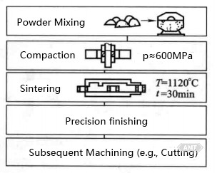
Figure 9-6 Conventional Production Process Route for Powder Metallurgy Oil Pump Gears
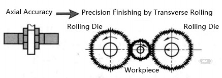
Figure 9-7 Alternative Finishing Method for Oil Pump Gears
To study the rolling process, a CNC-controlled rolling machine was employed. The machine structure includes two movable rolling dies and a workpiece fixed between them or mounted on a shaft. A small clearance transmission between the directly driven spindle and the motor facilitates the rolling of high-precision gears.
Figure 9-8 illustrates the surface roughness before and after rolling. Given the increased performance requirements (i.e., hardness, wear resistance, and dimensional accuracy), the rolling process was selected. SEM images clearly show the morphological changes of the gear surface after rolling, with the R value (a measure of surface roughness) reduced to approximately 1/10 of its original value. Pump tests indicated that the wear of the rolled gear surfaces was reduced.
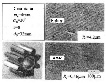
Figure 9-8 Surface morphology of oil pump gears and key tooth profiles before and after compaction
In addition to enhanced wear resistance, dimensional accuracy of the rolled gears must be ensured. Therefore, the tooth profiles of the pre-formed gears and rolling dies must be carefully designed, as shown in Figure 9-9.
Based on the tooth profiles and gear data of both parties, the gear flank and tooth slot can be formed. Subsequently, rolling simulations can be conducted, and the tooth profile of the rolling die can be calculated.
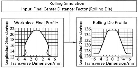
Figure 9-9 Design Principle of Rolling Die
A new design concept is adopted.
Then, the gear profile can be used to manufacture the rolling die. Changing the input gear data will result in different tooth profiles of the rolling die, which can be used to optimize the dimensional accuracy of the rolled pump gears.
The above sections have explained how to improve pump efficiency through tooth profile optimization and process changes (e.g., rolling) without increasing production costs. Another way to enhance pump efficiency is by adopting a new design concept.
The planetary gear rotor pump (Figure 9-10) is an outstanding example of a high-efficiency pump design. This pump can be used in applications with pressure levels up to 16 kPa and features a compact component size. This type of pump can easily compete with vane pumps and crescent pumps, and in terms of efficiency, it can even surpass piston pumps. An additional advantage of the planetary gear rotor pump is its lower pulsation, resulting in much smoother operation.
The primary geometric shape of the planetary gear rotor pump is similar to that of a conventional rotor pump. The main difference lies in the incorporation of small planetary gears within the outer rotor. These small planetary gears are designed to create synchronized, self-sealing macro and micro gear contact surfaces. This design ensures excellent sealing at the gear tips (the area with the largest leakage in rotor pumps), resulting in minimal losses. The volumetric efficiency primarily depends on the axial clearance. Tests on powder metallurgy planetary gear rotor pumps have demonstrated the utilization of self-sealing characteristics from the very beginning of operation.
Compared to industrial crescent pumps (designed to operate at pressures up to 25 kPa with axial clearance pressure compensation), the planetary gear rotor pump exhibits an increase in volumetric efficiency of approximately 1.5% within the pressure range up to 12 kPa, without any axial clearance pressure compensation. This high volumetric efficiency potential is a direct result of the practical principles of the planetary gear rotor pump. The superior performance of the planetary gear rotor pump makes it suitable for numerous applications in the automotive industry, such as automatic manual transmissions (AMT), dual-clutch transmissions, continuously variable transmissions (CVT), 4WD lock differential slip connections, or other applications requiring high efficiency and compact components.
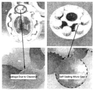
Figure 9-10 Comparison between Traditional Cycloid Rotors and Planetary Gear Rotors
Another critical issue in oil pump design is the internal leakage caused by the axial clearance between the rotor pair and the pump housing. For high-pressure applications, mechanical methods are generally employed to reduce the gap at the pump end cover, thereby limiting leakage. However, in many automotive applications, cost-effective gap compensation is required within a wide temperature range for low to medium pressure levels. At these pressure levels, expensive mechanical pressure compensation methods offer limited efficiency improvements.
Since axial clearance is more dependent on temperature than pressure levels, compensating for axial clearance based on the thermal expansion of compatible materials is a suitable solution. Studies have been conducted on powder metallurgy steel rotor pairs and different housing materials, with results shown in Figure 9-11.
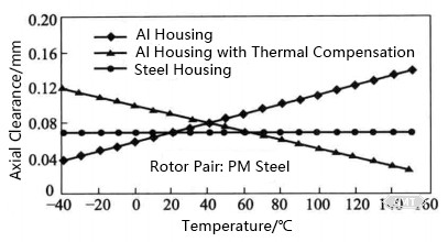
Figure 9-11 Compensation for axial clearance due to thermal expansion
In the case of a steel housing, the axial clearance between the powder metallurgy steel rotor pair and the housing remains constant within the listed temperature range. For the powder metallurgy steel rotor pair in an aluminum housing, the axial clearance increases with rising temperature.
Thermal axial clearance compensation involves adding a sleeve made of a material that replaces the aluminum pump housing or cover. The CTE (coefficient of thermal expansion) of the material used for these sleeves must be approximately one order of magnitude smaller than that of the pump rotor pair. As shown in Figure 9-11, with increasing temperature, the thermal compensation axial pump volumetric efficiency remains unchanged.
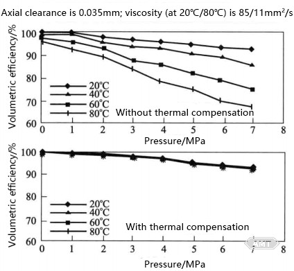
Figure 9-12 Volume efficiency with and without thermal compensation (powder metallurgy steel rotor pair/aluminum shell)
Another method to overcome the axial mismatch between cast aluminum pump housings and powder metallurgy steel rotor pairs is to use a material with a CTE similar to aluminum. One possible solution is to employ a stainless steel (e.g., 316 stainless steel: CTE = 1.8 ×10⁻⁵℃-1) rotor pair. In this case, the difference in CTE between the rotor pair material and the housing material (aluminum casting: CTE = 1.8 × 10⁻⁵℃-1) is about 10%.
An alternative approach is to develop powder metallurgy aluminum alloys as materials for pump rotor pairs. GKNSinterMetals has developed new load bearing aluminum alloys and new production processes for sintered special aluminum alloys.
It is known that adding Si to cast aluminum alloys can improve wear resistance. An important advantage of powder metallurgy is the ability to select over-eutectic Al-Si alloys with unique microstructures. Therefore, high silicon aluminum alloy products made by powder metallurgy are of great significance.
A special process for powder metallurgy alloys with a chemical composition of Al-14Si-2.5Cu-0.5Mg. The microstructure of this alloy material (Figure 9-13) consists of an aluminum alloy matrix and uniformly distributed fine Si particles that enhance wear resistance.
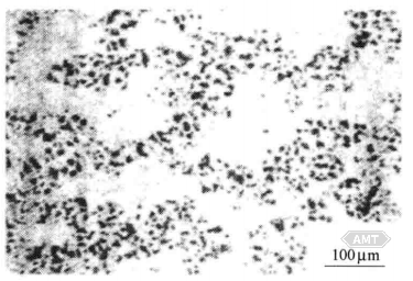
Figure 9-13 Optical microstructure photo of sintered alloy
The CTE of this alloy is almost identical to that of conventional Al-Si casting alloys generally used for pump housings. This ensures minimal axial clearance and optimal efficiency across a wide temperature range. Additionally, due to the excellent wear resistance of rotor pairs made from powder metallurgy Al-Si alloys, this combination of properties significantly improves the performance of rotors in cast aluminum housings.
The above sections have explored four avenues for improving pump efficiency: optimizing gear pump gear tooth profiles, adopting new finishing processes-rolling, selecting compatible materials, and changing design concepts.
As shown in Figure 9-14 and Table 9-4
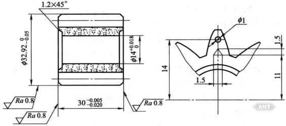
Figure 9-14 Oil Pump Gear (I) Drawing Gear precision ISO6 grade; gear end face deburring
Table 9-4 Gear Parameters
Item | Parameter |
Number of Teeth | 9 |
Module/mm | 2.9728 |
Pressure Angle/(°) | 25 |
Pitch Diameter/mm | 0.3569 |
Bore Diameter/mm | φ26.7552 |
Root Diameter/mm | φ20.75 |
2 Times Pitch Line Length/mm | 13.725-0.02 |
Application: Santana sedan engine oil pump.
Material and Treatment:
Material Composition: Cu 1%~5%, Content not exceeding 0.3%, Fe balance.
Density: 6.4~6.8 g/cm3;.
Sintering Conditions: 1150℃, 60 min.
Mechanical Properties: Tensile strength ≥ 230 MPa, Hardness ≥ 65 HB.
Performance Advantages: Good wear resistance, low noise.
Economic Benefits: Direct forming, low cost.
Manufacturer: Shanghai Powder Metallurgy.
As shown in Figure 9-15 and Table 9-5
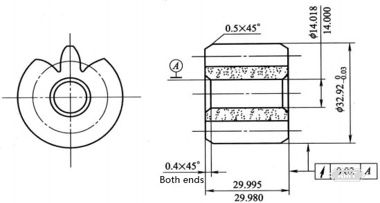
Figure 9-15 Oil Pump Gear (II) Drawing
Table 9-5 Gear Specification Details
Item | Parameter |
Number of Teeth | 9 |
Module | 2.97280 |
Pressure Angle | 25 |
Pitch Diameter | φ26.7552 |
Root Diameter | φ20.50 |
Addendum | 0.3569 |
Application: Automotive gear pump.
Material and Treatment:
Material Composition: Fe-C-S.
Density: 6.3~6.5 g/cm3.
Sintering Conditions: 1150℃, 60 min.
Post-processing: Boring of inner hole.
Mechanical Properties: Single-tooth bending load not less than 14709 N, Hardness 70~100 HB.
Performance Advantages: Good wear resistance, low noise.
Economic Benefits: Significant reduction in production cost.
Manufacturer: Changchun First Automobile Works Radiator Factory.
As shown in Figure 9-16
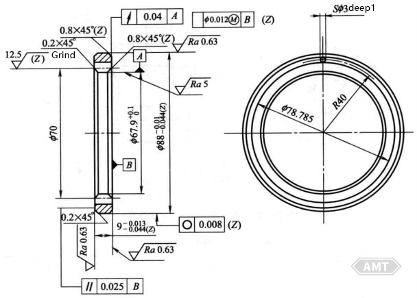
Figure 9-16 Oil pump ring gear parts diagram
Application: Automotive engine oil pump.
Material and Treatment:
Material Composition: Fe balance.
Density: 6.8 g/cm3 for the gear section, with a difference of 0.2 g/cm3 for the remaining parts.
Mechanical Properties: No cracking allowed.
Post-processing: Grinding of two planes and outer circle.
Performance Advantages: Compared to steel machined parts, due to lower roughness and oil impregnation, it offers better wear resistance and lower noise.
Economic Benefits: Material-saving, reduced man-hours, lower cost.
Manufacturer: Chongqing Huafu Powder Metallurgy Factory.
As shown in Figure 9-17 and Table 9-6
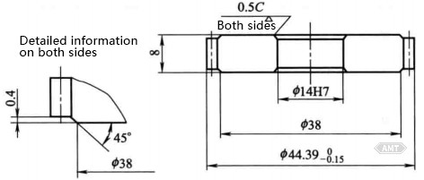
Figure 9-17 Oil Pump Driven Gear Drawing
Table 9-6 Gear Parameters
Item | Parameter | |
Gear Type | Spur Gear | |
Tooth Form Base Circle Section | Module | |
Tool | Shape | Normal Tooth |
Module | 1 | |
Pressure Angle | 20 | |
Number of Teeth | 42 | |
Helix Angle and Direction | 4°30′, Left | |
Reference Pitch Diameter | 42.13 mm | |
Tooth Thickness | Rolling Diameter/mm | 44.260.02 |
Pitch Diameter/in | 1/16 | |
Standard Rack Tooth Thickness |
| |
Correction Coefficient | 0.1244 | |
Standard Chamfer Depth/mm | 2.25 | |
Notes:
The total run-out of both sides relative to φ14mm is less than 0.1.
The total run-out of the gear face relative to φ14mm is less than 0.1.
1in = 25.4mm.
Application: Driven gear for automotive oil pump.
Material and Treatment:
Composition: Cu 1%~3%, Ni 1%~3%, C 0.6%~0.85%, other elements less than 1%, Fe balance.
Density: Greater than 6.7 g/cm3.
Unit Mass: Approximately 67g.
Heat Treatment: Carburizing, quenching, and tempering.
Machining: Locations marked with ▽ in the drawing.
Mechanical Properties: Hardness greater than 60 HRA, case depth greater than 0.4mm.
Performance Advantages: Due to oil immersion, it offers self-lubrication, good wear resistance, low noise, and smooth rotation.
Rotor Parts Drawing As shown in Figure 9-18
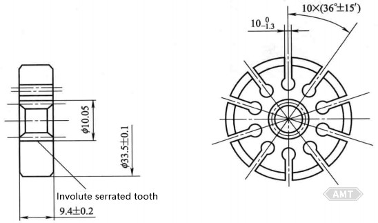
Figure 9-18 Rotor Parts Drawing
Application: For power steering pumps in sedans.
Material and Treatment:
Material Composition: Fe-1.5Cu-4Ni-0.5Mo-0.5C (carburized).
Density: 7.3 g/cm3.
Manufacturing Process: Compacting, sintering, carburizing, quenching, and tempering.
Features: The adoption of high-strength powder metallurgy materials with tensile strength greater than 980.6 MPa has enabled the transition from cast alloys to powder metallurgy materials. For high-density powder metallurgy parts, innovative thinking is required in mold structure and forming methods for 10 micro-gaps of 1.3mm width.
The pump consists of a pump body and aluminum base, utilizing four powder metallurgy parts——slider, rotor, pump body, and cover with a total mass of 1.46 kg. Both the powder metallurgy cover and aluminum base are ground to a flatness of 0.01 mm. To meet the pump's performance specifications and compatibility with the transmission valve body, the base is designed as an aluminum casting. In addition to product design, Stackpole conducted performance tests, including hot testing, cold testing, acoustic testing, and 1000-hour durability testing. Powder metallurgy can save costs by no less than 20%. This pump features variable displacement, allowing it to adjust flow and pressure according to demand. Compared to fixed-flow pumps, it significantly improves mechanical efficiency. Post-processing of the powder metallurgy parts includes steam treatment, high-frequency quenching, and double-sided grinding.
This oil pump is used in the GM 4T40E/45E 4-speed automatic transmission.
Figure 9-19 Transmission Oil Pump
Leave your email for more ebooks and prices📫 !
Contact:Fidel
Tel:021-5512-8901
Mobile:19916725893
Email:sales7@atmsh.com
Address:No.398 Guiyang Road Yangpu China