
Date:2025-07-18 Views:1001
Table of contents
Improvements and Innovations in Rotor Design
High-Performance Oil Pump Gear for Automotive CVT
High-Dimensional Accuracy Oil Pump Gear Made by Hardening in Molds
High-Efficiency Powder Metallurgy Rotor with Newly Developed Gear Profile
The internal gear design (Figure 9-20) allows the operating pressure to be increased to 16MPa. Given the high frequency of stress on the material due to the circular and symmetrical nature of the components, production can be challenging. The size and pressure range of these pumps are somewhat limited, primarily due to the surface stress that the material can withstand. These pumps also feature end plates or porting plates, which are generally manufactured using powder metallurgy processes.
Due to the lower rotational speed of the rotor elements and the direction of rotation being the same as that of the internal rotor advancing by one tooth per revolution, material issues are simplified. In some cases, the relative speed between surfaces may be as low as 1/7 of the shaft speed. Replacing the solid teeth in the external rotor with rolling elements can further enhance material adaptability, and the free rotation of these elements can reduce sliding.
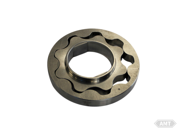
Figure 9-20 Rotor pump
This gear profile design, also known as the "iPR" design, has the following characteristics:
High Flow Rate: Optimized through simulation analysis to minimize fluid pulsation.
Low Friction: The contact surfaces between the inner and outer rotors are perpendicular to the direction of rotation, reducing friction.
Low Noise: Reduced gaps minimize noise from gear meshing, while maintaining constant torque.
(1) High Flow Rate
As shown in Figure 9-21, the oil pump structure and multi-tooth rotor profile are designed such that the effective volume on the intake side increases and decreases on the outlet side as the inner rotor rotates. This creates a vacuum on the intake side and pressure on the outlet side, enabling the rotor to pump oil. The inner rotor rotates counterclockwise, drawing oil from the intake side through the intake port to the outlet side.
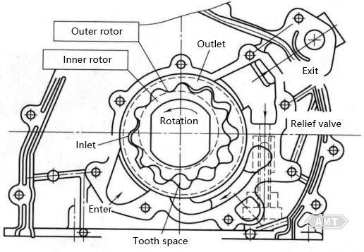
Figure 9-21 Oil Pump Structure and Multi-Tooth Rotor Profile
To prevent the rotor system from exceeding the oil pressure at the outlet, a pressure relief valve is installed. Focusing on the maximum flow rate of the rotor system, this is where cavitation, pressure pulsation, and pressure loss occur. A special relationship exists between the rotor profile and flow rate variation, as shown in Figure 9-22.
In Figure 9-22 (a), V represents the volume between the inner and outer rotors at an angle of θ. In Figure 9-22 (b), the X-axis is the rotational axis of the inner rotor, and the Y-axis is the flow rate. The flow rate is calculated by dividing the differential of the flow rate by the area S. Data for both standard and iPR rotors are shown in Figure 9-22 (b), indicating that the peak flow rate of the iPR rotor is much higher than that of the standard rotor. By adopting the iPR profile, the inflow and outflow of fluid become more stable, leading to higher efficiency at the outlet. The relationship between rotor profile and fluid pulsation has been clarified, and the iPR design has been optimized. Figure 9-23 shows the maximum flow rate of the iPR design.
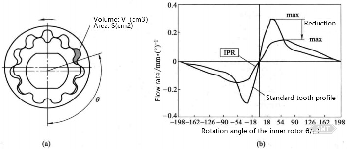
Figure 9-22 Area, Volume, and Rotor Angle (a) and IPR Maximum Flow Rate [dV/(dθ·s)] (b)
The fluid pulsation of the iPR design is reduced by 22% compared to the standard rotor design. Figure 9-24 illustrates the relative flow rates of the standard rotor and the iPR design, with the iPR design showing a 7% increase in flow rate.
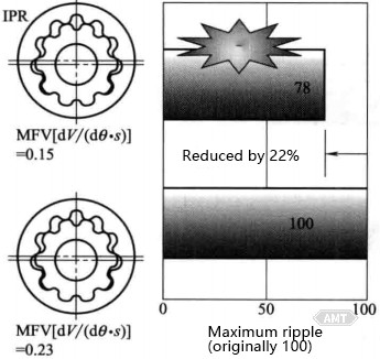
Figure 9-23 IPR Maximum Flow Rate [dV/(dθ·s)]
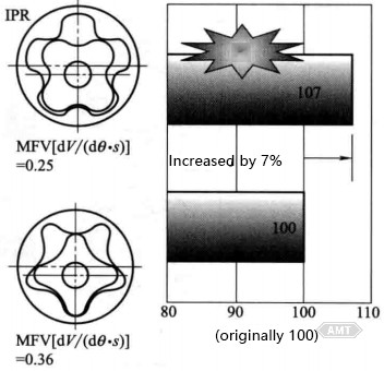
Figure 9-24 Flow Rate Comparison
(2) Low Friction
The contact surface between the rotors is analyzed. The contact points between the inner and outer rotors are located at the point where the rotation transitions from the inner rotor to the outer rotor. This indicates the vector of the outer rotor's movement from the contact point, which is divided into two components. One component is the tangential vector relative to the surface, and the other is the normal vector relative to the surface. The angle between the rotational vector and the normal contact surface vector is the pressure angle (α). The normal vector is the torque transmission component, while the tangential vector represents sliding. The greater the difference between the normal vector and the direction of the outer rotor's movement, the larger the friction (tangential) component, resulting in friction (torque) loss. Figure 9-26 illustrates the advantages of the iPR profile design. The difference between the standard rotor and the iPR profile is shown in the figure. The standard design has a pressure angle, but the iPR profile has a pressure angle α=0. By equalizing vectors A and B, the sliding component can be eliminated, meaning a reduction in sliding friction. Figure 9-27 shows the difference in torque loss between the iPR rotor and the standard rotor design.
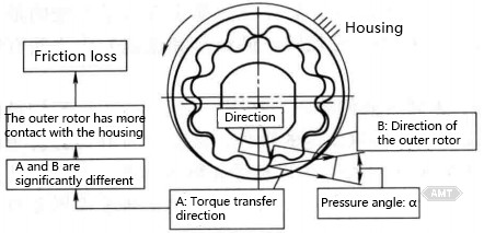
Figure 9-25 Tooth Profile Contact
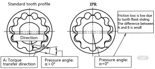
Figure 9-26 Advantages of IPR Gear Contact
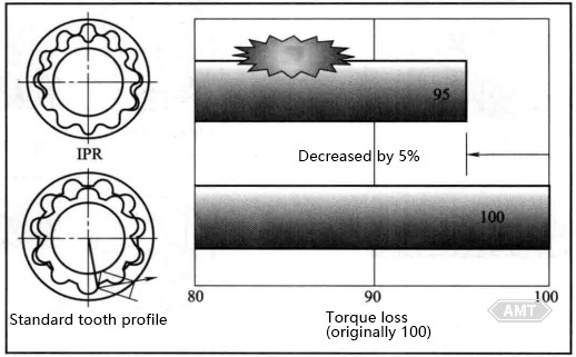
Figure 9-27 Tooth Profile Contact and Torque Loss
The torque loss of the iPR rotor is 5% less than that of the standard rotor design. Figure 9-28 highlights the advantages of the iPR hubless rotor design.
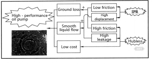
Figure 9-28 Advantages of Hubless Rotor
The advantage of the hubbed inner rotor design is that it can absorb crankshaft vibrations and reduce oil leakage. Typically, the hub is sealed with the housing to eliminate oil leakage. However, hub design requires machining, which increases costs. By eliminating the hub of the inner rotor, friction can be reduced. Without a hub, minimal oil leakage may occur. Considering the elimination of the hub and the inherent low friction of the iPR design, torque loss can be effectively reduced. Regarding oil leakage, the iPR design inherently has a higher flow rate, which can compensate for the leakage. These factors have led to the production of a high-performance oil pump with low cost, low torque loss, and stable fluid flow.
(3) Low Noise
In the standard rotor design, noise is generated at low RPM due to low-frequency vibrations and at high RPM due to cavitation. By optimizing the pump's clearances and reducing oil pressure pulsations, low RPM noise can be eliminated. The iPR rotor's minimized clearance function helps reduce RPM-related noise. With its smaller clearances and reduced friction, the iPR design also minimizes the potential for dynamic interference. There are three methods to reduce high RPM rotor noise: ① Design the inlet for low suction pressure; ② Design the outlet for low cavitation; ③ Stabilize the pump's maximum flow rate to eliminate high RPM cavitation noise. All these methods have been incorporated into the iPR design. Figure 9-30 shows the clearances of the inner and outer rotor profiles (or tooth tips) in three different regions.
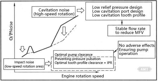
Figure 9-29 Technical Highlights of Low-Noise Oil Pump

Figure 9-30 Gear Tooth Clearance
In the standard design, the maximum tooth tip clearance is at the "a" position of the driving tooth, reducing to the sealing tooth position "c". In the iPR design, the overall clearance is smaller and never exceeds that of the standard design.
Both automotive AT (Automatic Transmission) and CVT are equipped with oil pumps. However, energy loss due to friction between the pump gears and the pump housing is a concern. Moreover, the operating pressure for CVT oil pump gears is higher than that for AT, making energy loss a significant issue.
Although crescent-shaped gears are commonly used to ensure precision, gear designs without crescent shapes feature hypoid curves. The following measures have been taken to improve oil discharge performance and prevent gear damage: ① Reduce the absolute value of the top clearance to 2/3 of that in previous AT gears; ② Enhance strength through heat treatment. As a result, CVT pump energy loss has been reduced, contributing to improved automotive fuel consumption.
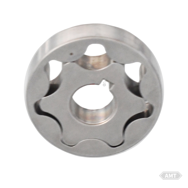
Figure 9-32 Oil Pump Gear
Conventional hardening processes increase production costs. The new process involves heating parts to the austenitizing temperature of the material, cooling them in oil, and before the martensitic transformation begins, removing them from the hot oil. They are then finished and cooled in a mold below the martensitic transformation temperature. This achieves high dimensional accuracy and hardness. Consequently, the pump rotor meets the required wear resistance and gear profile accuracy, reducing production costs by 50%.
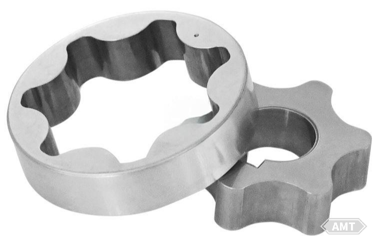
Figure 9-33 Oil Pump Gear
Developing high fuel efficiency vehicles is essential due to ecological demands. Mitsubishi Materials Corp. collaborated with customers to improve mechanical efficiency by reducing friction. Conventional oil pumps directly connected to the crankshaft have an "inlet-low point" on the inner rotor to maintain engine speed. However, reducing the friction area is effective for minimizing friction. Mitsubishi Materials Corp. aimed to eliminate the "inlet-low point." Removing it increases the inner rotor's load. To address this, they: ① Enhanced material strength; ② Improved inner rotor bore precision (by over 65%); ③ Developed a new gear profile for smooth oil suction and low noise.
Additionally, to reduce the friction area, Mitsubishi Materials Corp. developed a narrower outer rotor (3.3mm, the maximum width for required strength). This narrower outer rotor reduces friction by 12.5% and part weight by about 30%, significantly lowering production costs.
Figure 9-34 Internal Gear Pump Rotor
Despite the strong demand for reduced automotive fuel consumption, oil pump energy consumption remains significant, accounting for about 10% of engine oil pump energy and 20-30% of automatic transmission oil pump energy. Users require high-efficiency oil pumps to improve fuel efficiency.
The energy consumption of gear oil pumps depends on friction losses affected by the rotor's side and the outer rotor's outer surface. To reduce friction losses, a new gear profile was developed to increase theoretical displacement from the same outer diameter of the outer rotor.
The conventional inner rotor profile has one base circle, with the displacement-related movement distance determined by the base circle and the number of teeth. Since theoretical displacement depends on the movement distance and one base circle, the new inner rotor profile features two base circles, with the profile between them being an involute curve. The outer rotor profile is designed based on the inner rotor's profile. Through theoretical calculations and prototype testing, design parameters were optimized. The new gear profile's inner gear rotor has a larger movement distance.
Thus, the theoretical displacement of the newly developed internal gear rotor is 12% higher than that of a conventional rotor of the same size (actual displacement is 10% higher). Maintaining a constant actual displacement allows for a smaller rotor and reduced energy consumption. This size reduction enables the newly developed oil pump to have a drive torque about 10% lower than conventional oil pumps.
The hypoid rotor is shown in Figure 9-35.
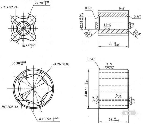
Figure 9-35 Hypoid Rotor
Applications: Automotive hypoid pumps.
Materials and Treatment
Composition: 0.6%~1.0% C, Fe balance.
Density: 6.3~6.5 g/cm3.
Sintering Conditions: 1200℃, 60 minutes.
Machining: As indicated by ▽ in the figure, machining is performed before turning.
Mechanical Properties: Tensile strength >245.3 MPa, hardness >40 HRB.
Advantages and Disadvantages: Due to its complex shape, it is very advantageous compared to other manufacturing methods.
Economic Benefits: There is almost no comparative data available as no other method has been used for production.
The oil pump rotor is shown in Figure 9-36.
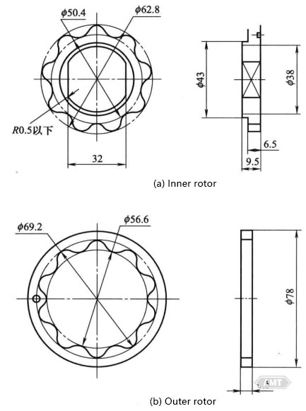
Figure 9-36 Oil Pump Rotor I
Applications: Engine lubrication, power steering.
Materials and Treatment
Composition: Fe balance.
Density: 6.8 g/cm3.
Mechanical Properties: J/cm3.
Manufacturing Process: Forming - Sintering - Finishing - Machining.
Features: Features a hypoid tooth profile, suitable for miniaturization and weight reduction of pumps. Powder metallurgy can produce cost-effective and high-quality products. When using high-strength sintered materials or sintered stainless steel, the application scope can be further expanded.
The oil pump rotor is shown in Figure 9-37.
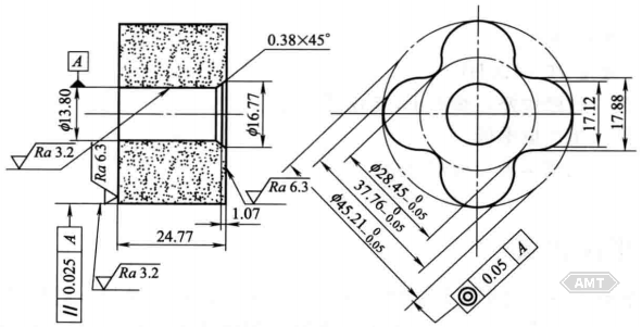
Figure 9-37 Oil Pump Rotor II
Applications: Automotive gear pump.
Materials and Treatment
Composition: Fe-C-S.
Density: 6.3~6.5 g/cm3.
Sintering Conditions: 1150℃, 60 minutes.
Post-processing: Boring of inner hole.
Mechanical Properties: Hardness 60~100 HB.
Advantages and Disadvantages: Good wear resistance, low noise.
Economic Benefits: Material-saving, labor-saving, low cost.
The diesel pump inner rotor is shown in Figure 9-38.
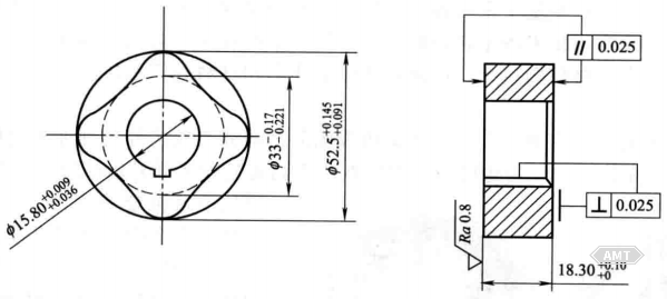
Figure 9-38 Diesel Pump Inner Rotor
Applications: Diesel engines for 8-ton trucks.
Materials and Treatment
Composition: Fe-3Cu-1C-0.3S.
Density: ≥6.4 g/cm3.
Post-processing: Vibratory finishing.
Mechanical Properties: Hardness 70~120 HB.
Advantages and Disadvantages: Good wear resistance, low noise, stable oil pressure.
Economic Benefits: Low cost.
The diesel pump outer rotor is shown in Figure 9-39.
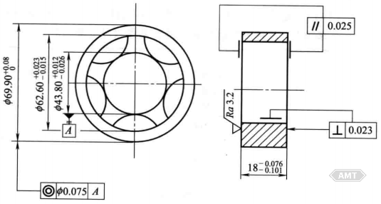
Figure 9-39 Diesel pump outer rotor
Applications: Diesel engines for 8-ton trucks.
Materials and Treatment
Composition: Fe-3Cu-1C-0.3S.
Density: ≥6.4 g/cm3.
Post-processing: Vibratory finishing.
Mechanical Properties: Hardness 70~120 HB.
Advantages and Disadvantages: Good wear resistance, low noise, stable oil pressure.
Economic Benefits: Low production cost.
Leave your email for more ebooks and prices📫 !
Contact:Fidel
Tel:021-5512-8901
Mobile:19916725893
Email:sales7@atmsh.com
Address:No.398 Guiyang Road Yangpu China